Chapter 3 – Inputs-Outputs
5 - X5 SERIAL LINK (Sub D 9 pins male)
Same connector for both 230 V and 400 V ranges.
GND (connection of the shield if no "360°" connection on the connector)
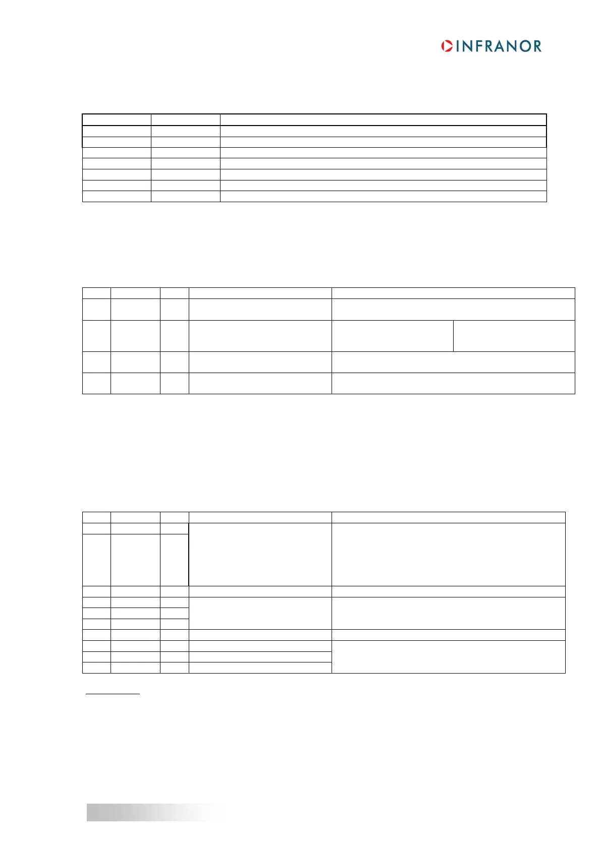
6 - X8: AUXILIARY SUPPLY CONNECTOR
Same connector for both 230 V and 400 V ranges.
4 pins male connector (with 5.08 mm pitch) - Female connector supplied
Fastening torque of the connector screws: 0.5 Nm
Potential reference of the
GND = earthed potential reference
24 VDC auxiliary supply mains
isolated
(without brake control)
Regulation with load: 3 %
Powerless brake : 24 Vdc / 1.5 A
Direct motor brake control
Grounded load output protected against short circuits
7- X9 POWER CONNECTOR: MAINS, MOTOR, BRAKING RESISTOR (CD1-a-230 V AND 400 V)
XtrapulsCD1-a-230/I: 10 pins male connector (with 5.08 mm pitch) - Female connector supplied
XtrapulsCD1-a-400/I: 10 pins male connector (with 7.62 mm pitch) - Female connector supplied
XtrapulsCD1-a-400/70 and 90 A: 10 pins male connector (with 10.16 mm pitch).
Female connectors supplied in 2 parts: 7 pins female, pins 1 to 7
and 3 pins female, pins 8 to 10 for the motor.
Fastening torque of the connector screws: 0.5 Nm
Power feedback during the motor
deceleration with high inertia and
speed
CD1-a-230/I: 100 Ohms/100W (dp 100/100)
CD1-a-400/1.8 to 7.2: 200 Ohms/100W (dp 200/100)
CD1-a-400/14: 50 Ohms/200 W (dp 50/200)
CD1-a-400/30 and 45: 33 Ohms/280W (dp 33/280)
CD1-a-400/70 and 90: 16.5 Ohms/560W (dp 16.5/560)
(Braking resistors must be ordered separately)
Parallel connection of the DC bus
CD1-a-230/I 230 VAC 1~ or 3~
CD1-a-400/I 400 to 480 VAC 3~
Parallel connection of the DC bus
Motor cable with earthed connection by means of
Faston socket and 360° shield connection on earthed
collar
IMPORTANT: The motor cable must be shielded and connected over 360° on collars mounted for this purpose on
the housing. The ground wire of the motor cable MUST be connected to the Faston socket marked with the GND
sign.
The ground reference must also be connected on the second Faston socket.
The installer of the drives has to use a UL Listed Quick connect for ground connection (0.250 inches or 6.35
mm wide nominal).
Field wiring terminals have to use copper conductors only.
Torque value for field wiring terminals: value to be according to the Recognized terminal block used.

 Loading...