5 - USE OF THE "CV0" INPUT
Response time = 500 µs.
During the drive operation in speed mode (CI logic input inactive), the activation of the CV0 input stops the axis
rotation (the deceleration time is depending on the value of the Accel/Decel time parameter).
During the drive operation in torque mode (CI logic input active), the enabling of the CV0 input applies a zero
current input command and the current reference is maintained at zero as long as the CV0 input is active.
6 - USE OF THE "AOK" OUTPUT
If any fault occurs, the drive is disabled.
If a fault occurs (except for the "Undervot." fault) the AOK relay contact opens.
Use the AOK relay contact as described in chapter 3, section 3.3 in order to allow the power voltage being
switched on after the initialization phase.
Remark: The "Undervolt." fault can be configured in the Setup menu of the VISUAL DRIVE SETUP software to
open the AOK relay contact.
7 - USE OF THE "RESET" INPUT
If the position initialization references must be kept when a stored fault is released on the drive or when the power
supply is cut-off, it must be possible to reset the faults via pin 13 of X2 without switching off the auxiliary 24 VDC
supply or to backup the 24 VDC supply by means of a 24 VDC battery (see chapter 4).
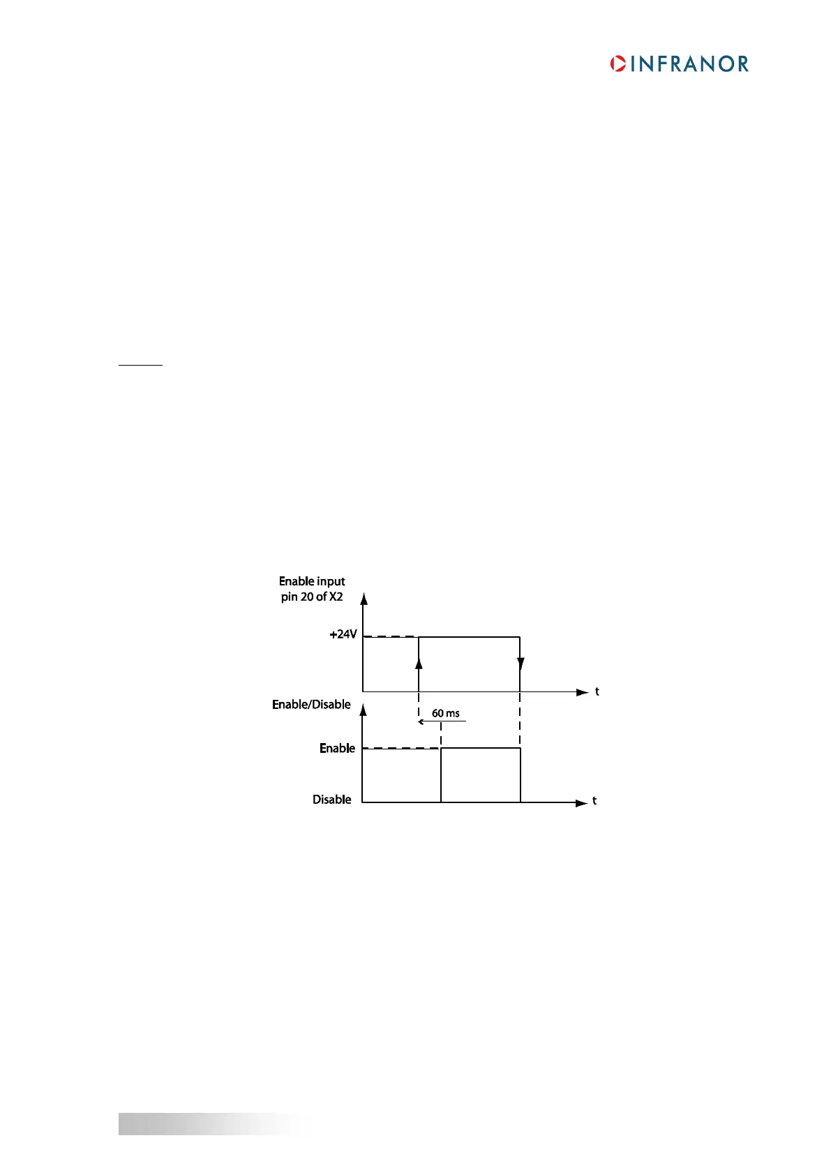
8 - USE OF THE "ENABLE" INPUT
The Enable input ensures the drive enabling/disabling as shown on the timing diagram below:
9 - USE OF THE "BRAKE" OUTPUT
The motor powerless brake type is controlled when the motor is enabled (ENABLE activated and no fault
displayed).