3.4 - POSITION FOLLOWING PROTECTION
The operation of the position following protection when selecting the Absolute mode in the Safety limits window
is described below.
The position loop error value is continuously compared with the value of the Following error threshold
parameter. When its value is exceeding the one of the Following error threshold parameter, the following error
is released.
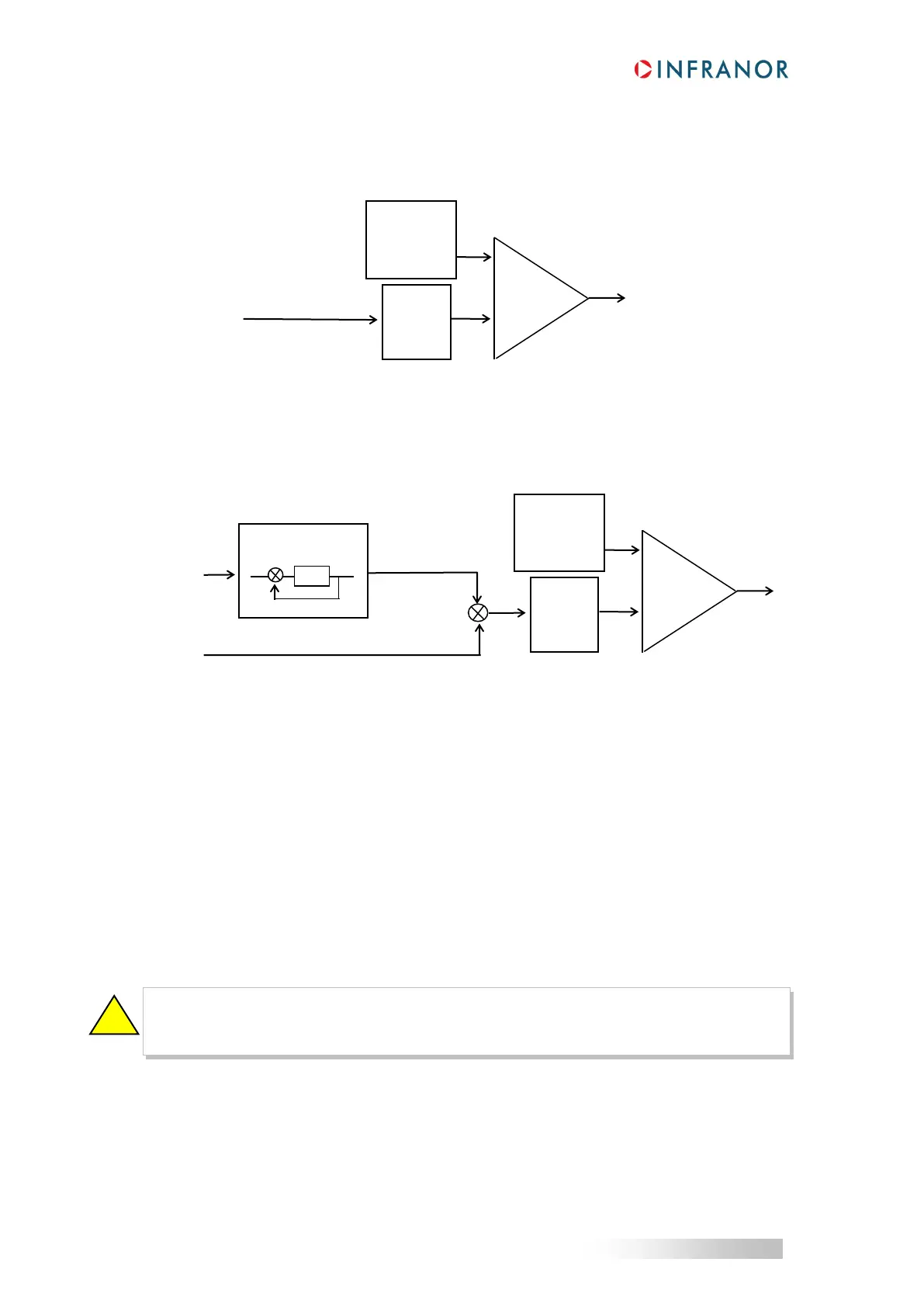
The operation of the position following protection when selecting the Relative to dynamic model mode in the
Safety limits window is described below.
The real value of the position loop error is continuously compared with the theoretical value of the position loop
error given by a calculation model. When the difference is exeeding the value of the Following error threshold
parameter, the following error is released. In this configuration, when the position loop adjustment is made without
anticipative speed term (Feedforward speed gain = 0) for getting a positioning without overshooting in "Stepper
motor emulation" applications, a very low threshold of the Following error threshold parameter can nevertheless
be adjusted in order to detect the smallest error on the axis.
4 - USE OF THE "LIMIT SWITCH" INPUTS
Response time = 500 µs.
During the drive operation in speed mode (CI logic input inactive) or in torque mode (CI logic input active), the
enabling of the FC+ limit switch inhibits any CW motor rotation and the enabling of the FC- limit switch inhibits any
CCW motor rotation. The motor is decelerating with the drive Maximum current value in order to get the shortest
possible braking time.
Positive and negative directions depend on the position feedback sensor (encoder or resolver) wiring
and also on the motor wiring. So, before mounting and wiring the limit switches, it is recommended to
define the positive and negative directions of the motor.
Following
error
threshold
Following
error
threshold
Theoretical
position error

 Loading...