Note 1:
The motor cogging torque value is checked at the drive power up. If it contains some errors (storage problems in
the drive memory), the EEPROM error is displayed and the Enable cogging torque compensation function is
disabled.
Note 2:
When exchanging an drive on an axis, the file of the adjustment parameters (*.PAR) as well as the cogging torque
file (*.COG) corresponding to the motor must be uploaded again.
Note 3:
When exchanging the motor or when disassembling the resolver sensor, the acquisition procedure must be
renewed.
16 - SYSTEM OF POWER FEEDBACK VIA A BRAKING RESISTOR
All XtrapulsCD1 drives are equipped with the power feedback system. When the motor is decelerating with high
inertia and high speed, the mechanical braking energy is reflected to the drive. This energy is dissipated inside a
resistor called "braking resistor".
In order to avoid heat dissipation inside the drive, the braking resistor is ALWAYS mounted outside. It MUST be
mounted out of range of heat sensitive and inflammable elements (plastic, cable sleeves, etc.).
For an optimum power feedback by the drives in a multiaxis application, the DC bus (DC+ and DC-) can be
parallel connected (see diagram in chapter 4, section 1.5).
In this case, the mains input must also be parallel wired in order to balance the current load inside the AC/DC
converters.
It is recommended to mount the braking resistor on the drive with highest current rating.
An electronic control of the dissipated power avoids the overloading of the braking resistor. So, if the energy
reflected to the drives with parallel mounted DC busses is too high, the DC bus voltage will rise up to the triggering
of the "Overvoltage" fault. A second resistor must then be mounted on the second axis.
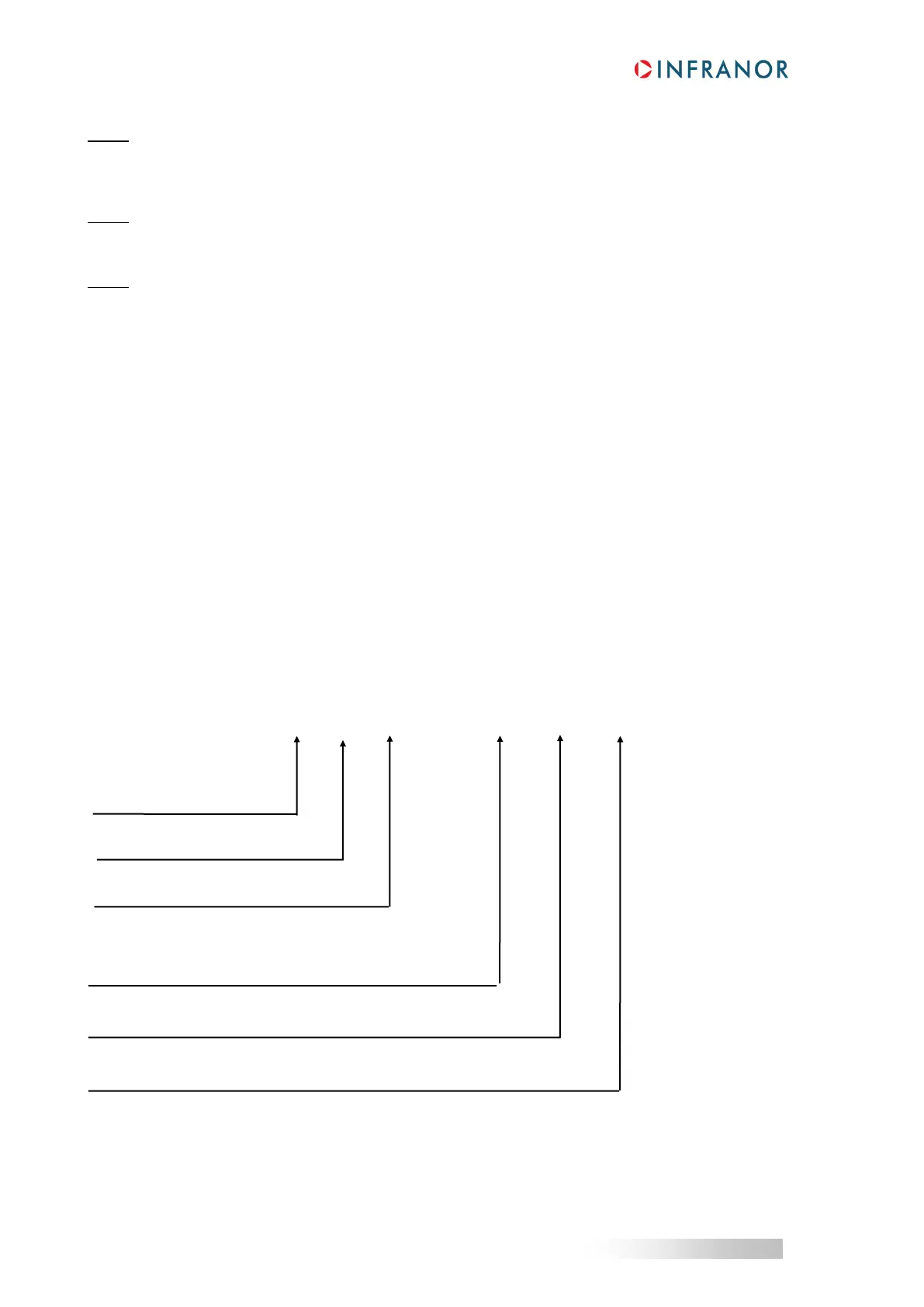
17 - ORDERING CODE
230 = 230 VAC operation voltage
400 = 400 or 480 VAC operation voltage
Xtrapuls CD1 - a - U / I - CT - RS
Current ratings:
2.25 / 4.5 / 7.5 / 10.5 / 16.5 Arms with 230 VAC
1.8 / 2.7 / 5.1 / 7.2 / 14 / 30 / 45 / 70 / 90 Arms with 400 VAC
RS-422 serial link option

 Loading...