3.2.2 - OPERATION OF THE CURRENT LIMITATION IN LIMITING MODE
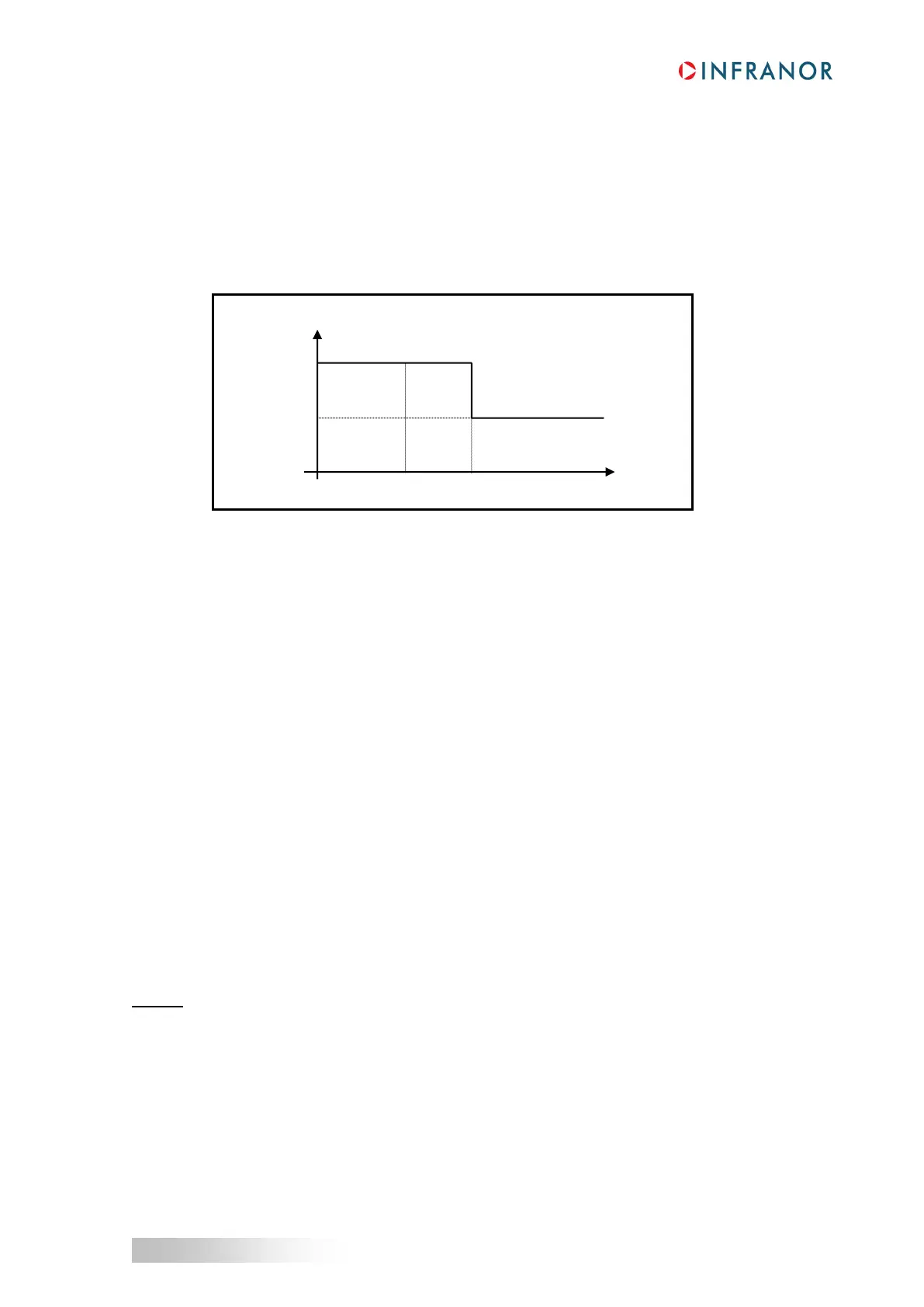
When the drive output RMS current (I
2
t) reaches 85 % of the rated current, the I²t fault LED on the drive front
panel is blinking (t1 in the diagram). When the RMS current (I
2
t) drops below 85 % of the rated current, the
blinking is inhibited.
When the drive output RMS current (I
2
t) reaches the rated current value, the I
2
t protection limits the drive output
current at this value (t2 in the diagram).
Diagram of the drive output current limitation in an extreme case (motor overload or shaft locked):
The maximum current duration before release of the blinking display (t1 - t0) and before limitation at the rated
current (t2 - t0) is calculated the same way as in the "Fusing" mode.
3.3 - ENCODER COUNTING PROTECTION
When servo motors are equipped with an encoder feedback, any error in the encoder pulses counting is
generating a rotor position measurement error and may involve uncontrolled motor movements that may be
dangerous for operator and machine. The encoder counting protection available in the XtrapulsCD1-a drive range
allows the detection of pulse counting errors and immediately disables the drive for safety reasons.
The encoder counting protection is checking that the number of encoder pulses between two successive Z marker
pulses (or R reference signals) is equal to the Motor encoder resolution value multiplied by the Zero mark pitch
parameter value. The encoder counting protection is also checking that the encoder pulses frequency is lower
than 1.5 times the maximum encoder frequency. The maximum encoder frequency is calculated in the drive
according to the Motor encoder resolution parameter value and the Maximum speed parameter value.
The Motor encoder resolution parameter value defines the number of encoder pulses (or encoder signal
periods) per motor revolution (for a rotary motor) or per motor pole pairs (for a linear motor).
The Zero mark pitch parameter value defines the number of motor revolutions (for a rotary motor) or of motor
pole pairs (for a linear motor) between two successive Z marker pulses (or R reference signals).
For a rotary motor, the Zero mark pitch parameter is generally equal to 1 because the encoder has got one Z
marker pulse (or R reference signal) per motor revolution.
For a linear motor with only one marker pulse over the entire motor travelling range, the parameter Zero mark
pitch must be set at 15. In this, case the encoder counting protection is checking that the measured encoder
position has always got the same value when the marker pulse is activated (no position measurement drift).
Remark: In the Incremental encoder configuration without HES, after a Counting fault release, it is necessary
to renew the motor Phasing procedure because the current rotor position reference for the motor commutation is
not correct.