Chapter 3 –Inputs-Outputs
(*)The 470 resistor is wired as from index:
There is no braking resistor on the former versions.
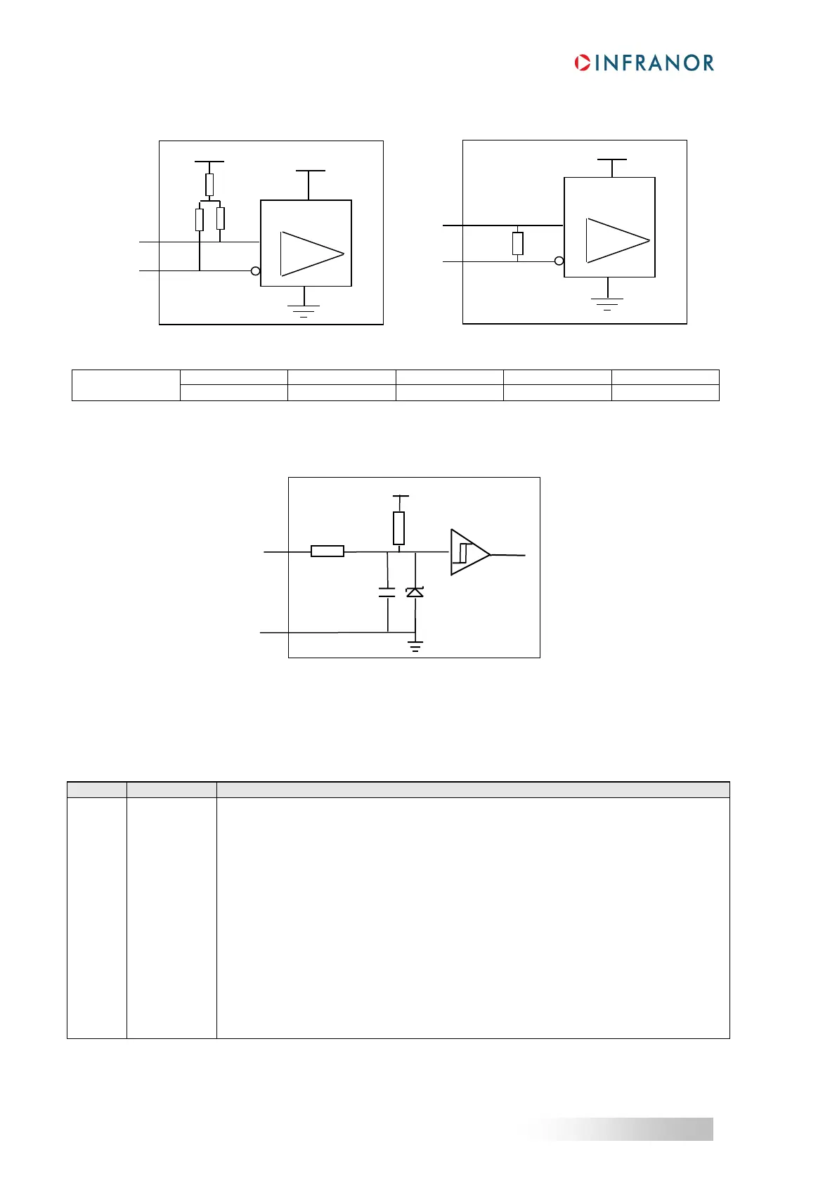
HALL SENSORS INPUT LINES SPECIFICATION
4.2 - X3 CONNECTOR FOR SinCos INCREMENTAL ENCODER & HES INPUT (Sub D 25 pins female)
The “ SinCos incremental encoder & HES” configuration is selectable by software and stored in the drive
EEPROM.
The corresponding X3 connector pin functions are described below.
Differential input of the Sin/Cos encoder reference pulse R/
Differential input of the Sin/Cos encoder reference pulse R
Differential input of the Sin/Cos encoder channel A/
Differential input of the Sin/Cos encoder channel A
Differential input of the Sin/Cos encoder channel B/
Differential input of the Sin/Cos encoder channel B
Encoder supply voltage (300 mA max. current)
Hall sensor input signal phase U
Hall sensor input signal phase V
Hall sensor input signal phase W
Hall sensors supply voltage: output impedance = 9 Ω, max 150 mA available
(1)
Motor thermal sensor input
Motor thermal sensor input
ENCODER INPUT LINES SPECIFICATION