EasyManuals Logo

Infranor XtrapulsGem Installation Guide

Default Icon
73 pages
To Next Page IconTo Next Page
To Previous Page IconTo Previous Page
Page #29 background imageLoading...
Page #29 background image
29
Chapter 3 Inputs-Outputs
XtrapulsPac Installation Guide
3.3 - X1 CONNECTOR
3.3.1 - XtrapulsPac-ak and XtrapulsPac-et versions
3.3.1.1 - X1 connector for transmitter resolver input (Sub D 15 pins female)
The Sub-D 15 pin female connector is compatible with the XtrapulsGem and XtrapulsCD1 series.
The “Transmitter resolver” configuration is software selectable and saved in the drive EEPROM.
PIN
FUNCTION
I/O
DESCRIPTION
1
Shield connection
I
The shield must have a 360° connection on the
connector metal cover. This connection can be
completed by connecting the wires to pin 1.
12
TC (thermal sensor)
I
Motor thermal sensor inputs. The valid
measurement range is between 100 and 44 k.
13
TC (thermal sensor)
I
2
S3 (cosine +)
I
Resolver signal
10
S1 (cosine -)
I
Resolver signal
11
S2 (sine +)
I
Resolver signal
3
S4 (sine -)
I
Resolver signal
5
R1 (reference +)
O
Resolver signal
4
R2 (reference -)
O
Resolver signal
6
Reserved
7,8,9
Reserved
14,15
Reserved
For the connection of other resolver types, see Chapter 5, section 1.
3.3.1.2 - X1 connector for SinCos tracks input (Sub D 15 pins female)
The “SinCos track” configuration is software selectable and saved in the drive EEPROM.
PIN
FUNCTION
I/O
DESCRIPTION
1
Shield connection
I
The shield must have a 360° connection on the
connector metal cover. This connection can be
completed by connecting the wires to pin 1.
12
TC (thermal sensor)
I
Motor thermal sensor inputs. The valid
measurement range is between 100 and 44
k.
13
TC (thermal sensor)
I
2
Cosine +
I
SinCos tracks signal
10
Cosine -
I
SinCos tracks signal
11
Sine +
I
SinCos tracks signal
3
Sine -
I
SinCos tracks signal
7
5 V
O
Sensor supply voltage (total external consumption
on all connectors = max. 300 mA)
8
GND
O
Sensor supply GND
6
External supply
O
Sensor supply voltage (if 5 V).
Supply to be provided via X2 connector, pin 3.
Only available from serial number 11043098.
4,5,9
Reserved
14,15
Reserved
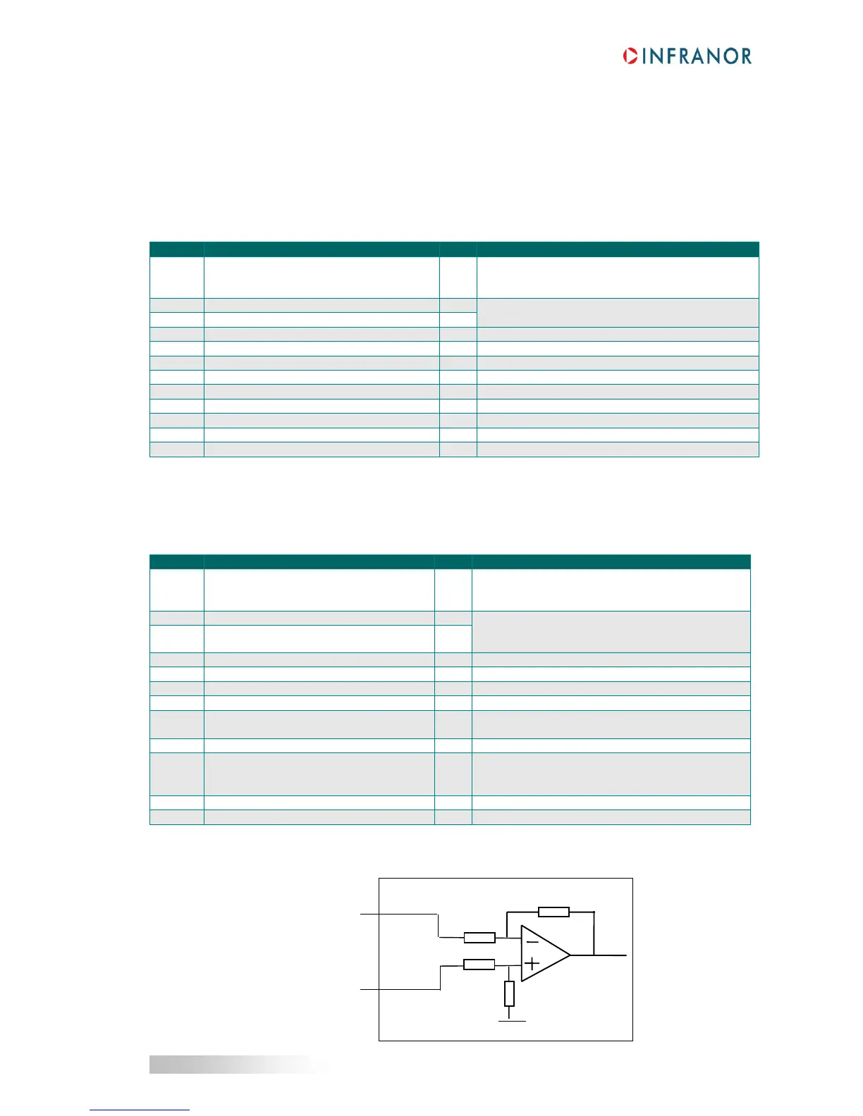
SPECIFICATION OF THE SINE AND COSINE CHANNELS
Sine-
Cosine-
Sine+
Cosine+
33K
33K
20K
20K
Uref
X1-3/10
X1-11/2

Table of Contents

Other manuals for Infranor XtrapulsGem

Questions and Answers:

Question and Answer IconNeed help?

Do you have a question about the Infranor XtrapulsGem and is the answer not in the manual?

Infranor XtrapulsGem Specifications

General IconGeneral
BrandInfranor
ModelXtrapulsGem
CategoryController
LanguageEnglish

Related product manuals