EasyManuals Logo

Infranor XtrapulsGem Installation Guide

Default Icon
73 pages
To Next Page IconTo Next Page
To Previous Page IconTo Previous Page
Page #37 background imageLoading...
Page #37 background image
37
Chapter 3 Inputs-Outputs
XtrapulsPac Installation Guide
3.6 - FIELDBUS CONNECTORS: X6 AND X7
3.6.1 - XtrapulsPac-ak version (CANopen® bus)
RJ45 standard connector
X6-PIN / X7-PIN
SIGNAL
DESCRIPTION
1
CAN-H
Line CAN-H (dominant high)
2
CAN-L
Line CAN-L (dominant low)
3
CAN-GND
CAN Ground
4
Reserved
5
Reserved
6
Internally connected
X6-pin 6 connected to X7-pin 6
Only available from serial number 11043098.
7
GND
8
Internally connected
X6-pin 8 connected to X7-pin 8
Only available from serial number 11043098.
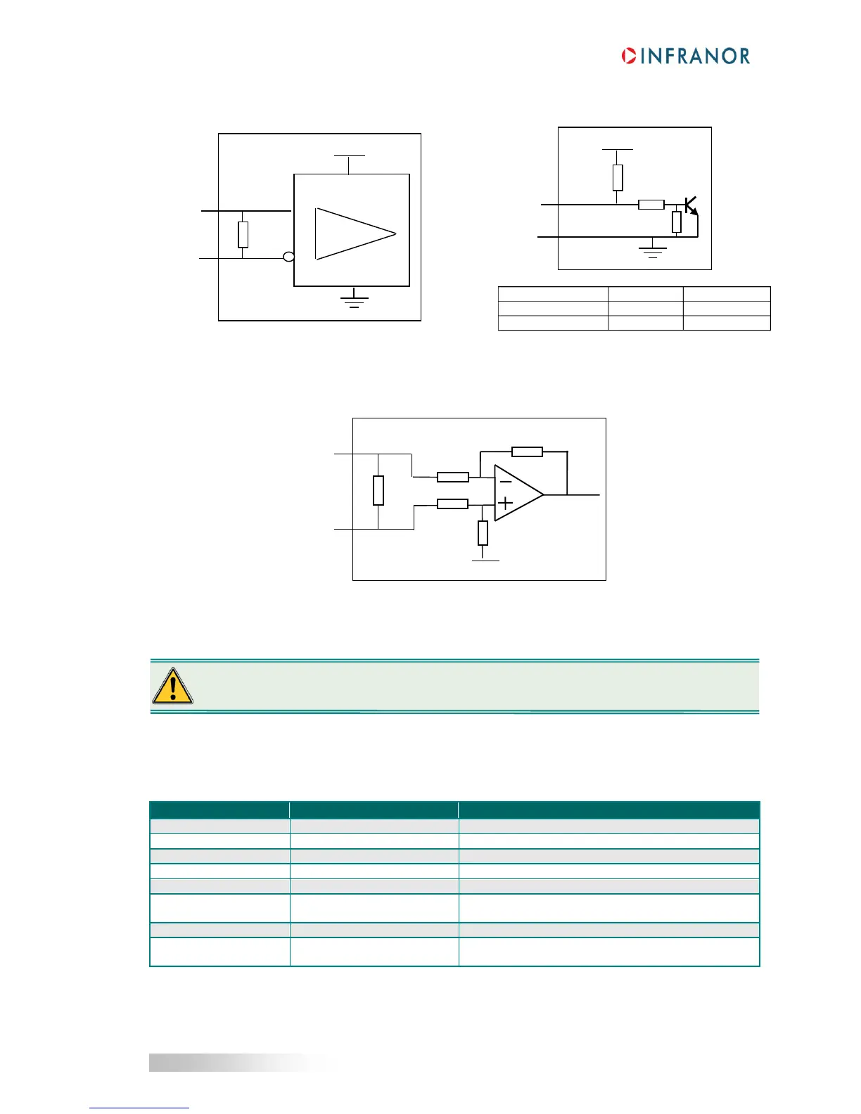
SPECIFICATION OF THE HALL
SENSOR INPUT LINES
+5V
10K
Hall U, V, W
GND
10K
10K
Min.
Max.
High input voltage
3.3 V
24 V + 15 %
Low input voltage
0 V
0.6 V
Hall inputs are compatible with open collector
outputs, without any external component.
Data+
A, B, Z
+5V
Receiver
75-176
660R
Data-
A/, B/, Z/
SPECIFICATION OF THE INCREMENTAL
TTL ENCODER INPUT LINES
SPECIFICATION OF THE SIN/COS AND HIPERFACE® ENCODER SIGNALS
Sin+ Cos+
Mark+
Sin- Cos-
Mark -
4,4K
120R
4,4K
10K
10K
Uref
In order to ensure the best reliability and performances of the global system, it is recommended to use
RJ45 Ethernet cables with a minimum level of category 5.

Table of Contents

Other manuals for Infranor XtrapulsGem

Questions and Answers:

Question and Answer IconNeed help?

Do you have a question about the Infranor XtrapulsGem and is the answer not in the manual?

Infranor XtrapulsGem Specifications

General IconGeneral
BrandInfranor
ModelXtrapulsGem
CategoryController
LanguageEnglish

Related product manuals