4.4 - ACCESSORIES AND CONNECTIONS
ENERGY RECUPERATION VIA A BRAKING RESISTOR
All XtrapulsPac stand-alone drives are fitted with the power feedback system. When the motor is decelerating
with high inertia and high speed, the mechanical braking energy is reflected to the drive. This energy is dissipated
inside a resistor called "braking resistor".
An electronic control of the dissipated power avoids the overload of the braking resistor. So, if the energy
reflected to the drives is too high, the DC bus voltage will rise up to the release of the "Overvoltage" fault.
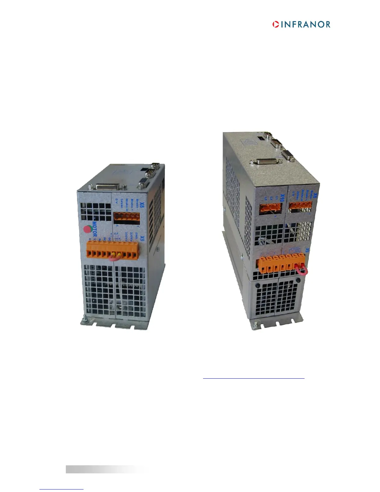
4.4.1 - Connection of the internal braking resistor
XtrapulsPac 230V XtrapulsPac 400V / 08 and 20 A
The XtrapulsPac drive in stand-alone version is equipped with an internal 35 W braking resistor.
Its connection is made by means of a wiring bridge between pins 6 and 7 of the X9 connector.
If the required rated power of the braking resistor is higher than 35 W or if the pulse power is higher than
1500 W, a larger external power resistor must be mounted (see manual "Braking resistors", section 2.1).
 Loading...

