Chapter 3 – Inputs-Outputs
XtrapulsPac Installation Guide
3.6.2 - XtrapulsPac-et and XtrapulsPac-ed versions (EtherCAT® bus)
RJ45 standard connector
For more information, see EtherCAT® fieldbus Interface manual.
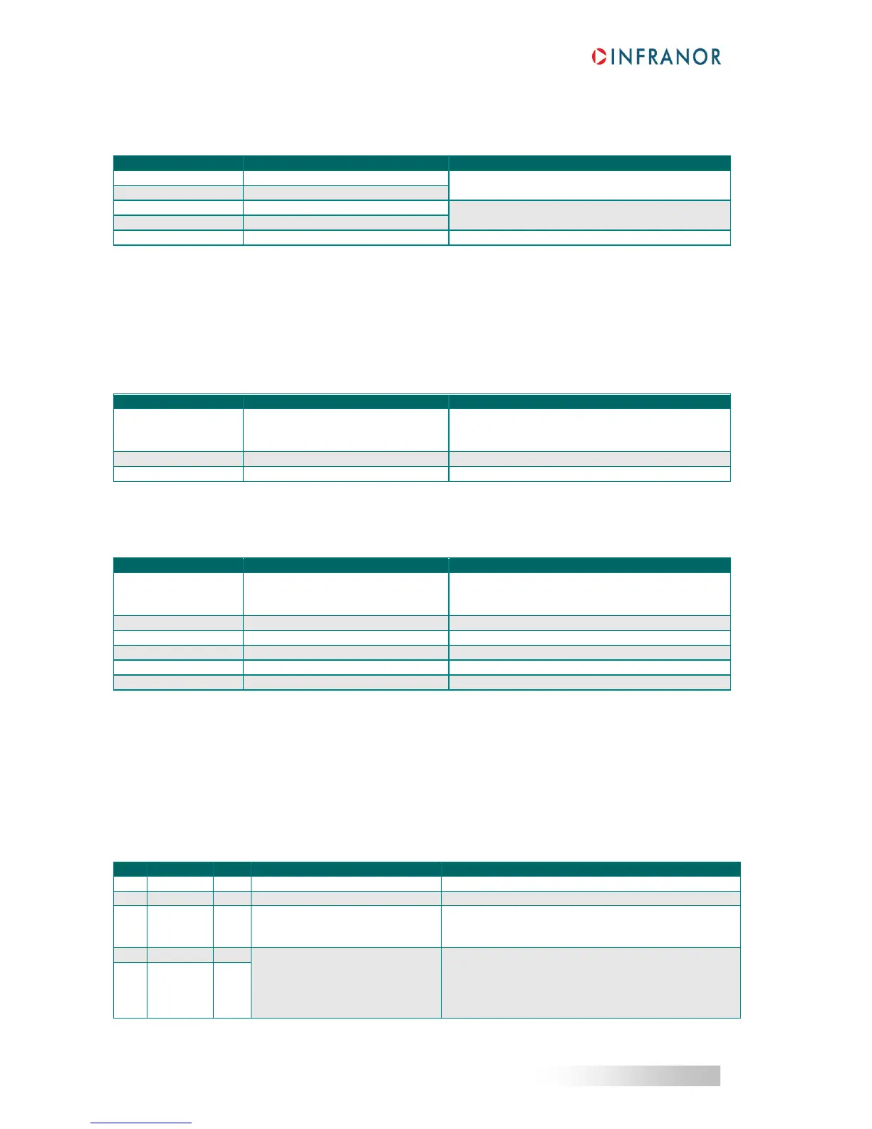
3.7 - SERIAL LINK RS-232 CONNECTOR: X5
3.7.1 - XtrapulsPac-ak version (CANopen® bus)
SUB D 9 pin male connector (same as XtrapulsCD1 and XtrapulsGem series)
GND (shield connection if no 360° connection on
the connector).
360° shield is strongly recommended.
3.7.2 - XtrapulsPac-et and XtrapulsPac-ed versions (EtherCAT® bus)
SUB D 9 pin male connector
GND (shield connection if no 360° connection on
the connector).
360° shield is strongly recommended.
Line CAN-H (dominant high)
Line CAN-L (dominant low)
In the EtherCAT® version, the multi-axis parameter setting and monitoring using the Gem Drive Studio software
can be performed via the CANopen® bus connection on the X5 connector.
3.8 - 24 V
DC
AUXILIARY POWER SUPPLY & MOTOR BRAKE CONNECTOR: X8
Manufacturer: Weidmüller
Type: BLZ 5.08 / 5
Reference: 152676
Tightening torque: 0.4 to 0.5 Nm
Grounded potential reference (GND reference)
24 V
DC
motor brake output
Signal connection for the motor
brake supply wiring relay
(optional)
Pins 2 and 3 internally connected on X8 for an easy
wiring in case of external brake relay.
Mains isolated 24 V
DC
auxiliary
power supply
0 V input referenced to the GND
potential on the drive housing
24 V
DC
supply: +/- 10 %
Consumption without brake:
400 mA for XtrapulsPac 230 V
500 mA for XtrapulsPac 400 V
UL: protection by means of a 3 A UL fuse
 Loading...

