Chapter 3 – Inputs-Outputs
XtrapulsPac Installation Guide
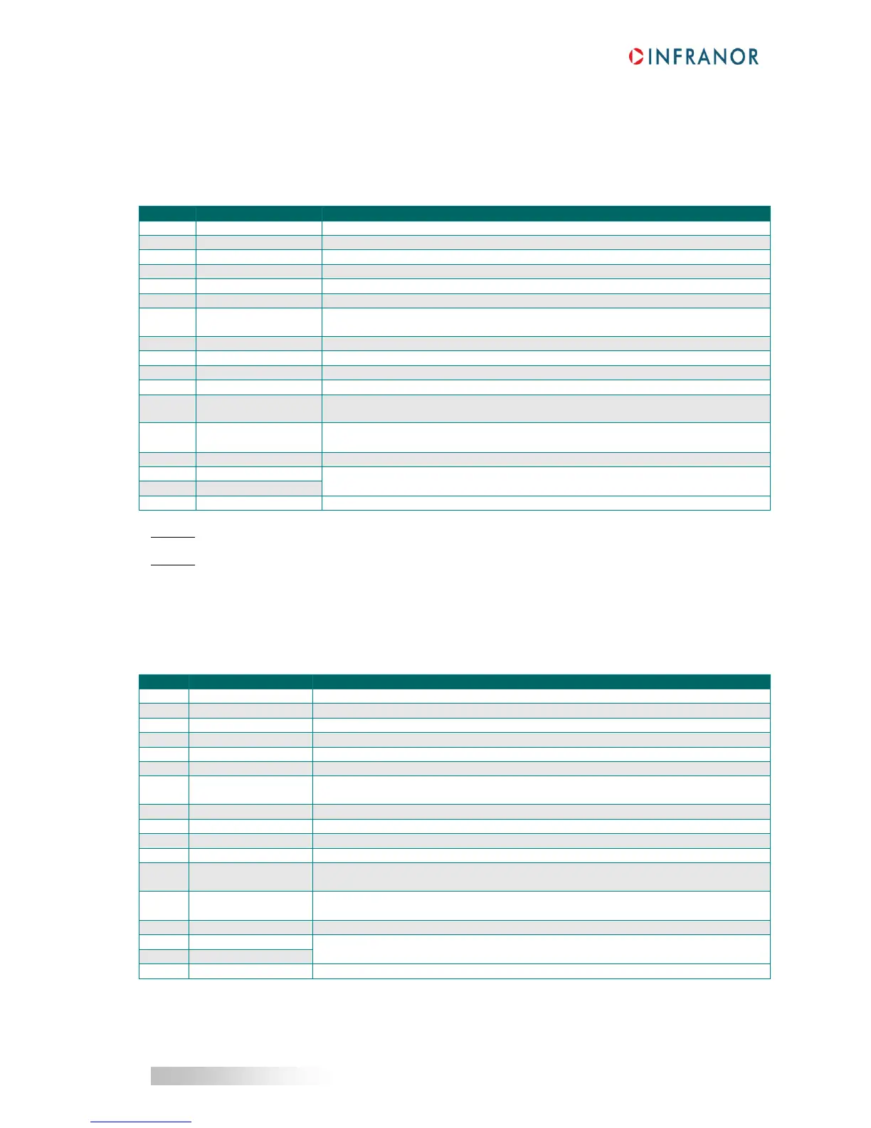
3.5 - ENCODER CONNECTORS: X3
3.5.1 - X3 connector for incremental TTL & HES encoder input (Sub D HD 26
pins female)
The “Incremental TTL & HES encoder” configuration is software selectable and saved in the drive EEPROM.
Differential input of the encoder marker pulse Z/
Differential input of the encoder marker pulse Z
Differential input of the encoder channel A/ (or PULSE/ for stepper emulation)
Differential input of the encoder channel A (or PULSE for stepper emulation)
Differential input of the encoder channel B/ (or DIR/ for stepper emulation)
Differential input of the encoder channel B (or DIR for stepper emulation)
Encoder supply voltage (total external consumption on all connectors = 300 mA
max.)
Hall sensor input signal phase U (or PULSE for stepper emulation)
Hall sensor input signal phase V (or DIR for stepper emulation)
Hall sensor input signal phase W
Hall sensor internal supply voltage 9.5 V +/- 0.5 V (150 mA max. output current).
Only available from serial number 11043098.
Hall sensor supply voltage (if 5 V
DC
or 9.5 V
DC
).
Supply to be provided via the X2 connector, pin 3.
Motor thermal sensor inputs. The valid measurement range is between 100 Ω
and 44 kΩ.
NOTE 1: A and B channels can be used as PULSE and DIRECTION inputs for the stepper motor emulation with
RS422 receiver interface.
NOTE 2: HALL U and HALL V inputs can be used as PULSE and DIRECTION logic inputs for the stepper motor
emulation with 5 V to 24 V logic interface.
3.5.2 - X3 connector for incremental Sin/Cos & HES encoder input (SubD HD
26 pins female)
The “Incremental SinCos& HES encoder” configuration is software selectable and saved in the drive EEPROM.
Differential input for the reference pulse of the Sin/Cos encoder channel Mark-
Differential input for the reference pulse of the Sin/Cos encoder channel Mark+
Differential input for Sin- channel of the Sin/Cos encoder
Differential input for Sin+ channel of the Sin/Cos encoder
Differential input for Cos- channel of the Sin/Cos encoder
Differential input for Cos+ channel of the Sin/Cos encoder
Encoder supply voltage (total external consumption on all connectors = 300 mA
max.)
Hall sensors input signal phase U
Hall sensors input signal phase V
Hall sensors input signal phase W
Hall sensor internal supply voltage 9.5 V +/- 0.5 V (150 mA max. output current).
Only available from serial number 11043098.
Hall sensor supply voltage (if 5 V
DC
or 9.5 V
DC
).
Supply to be provided via the X2 connector, pin 3.
Motor thermal sensor inputs. The valid measurement range is between 100 Ω and
44 kΩ.
 Loading...

