EasyManuals Logo

Infranor XtrapulsGem Installation Guide

Default Icon
73 pages
To Next Page IconTo Next Page
To Previous Page IconTo Previous Page
Page #56 background imageLoading...
Page #56 background image
56
Chapter 4 - Connections
XtrapulsPac Installation Guide
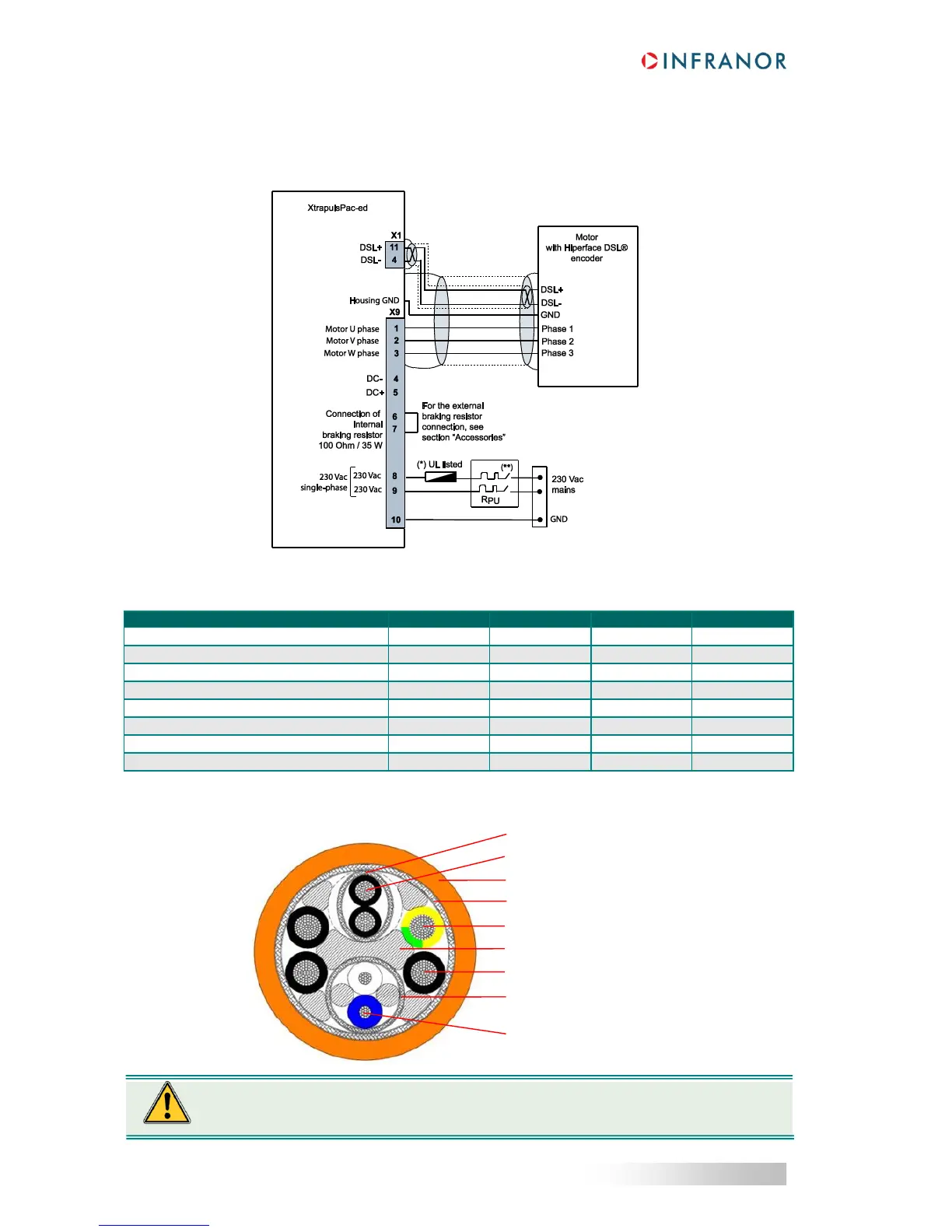
4.3.6 - Connection to an absolute Hiperface DSL® encoder: X1 - Sub D 15 pin
female connector
The two wires for Hiperface DSL® communication are integrated into the motor cable:
Hiperface DSL® cable specifications:
Property
Min
Typical
Max
Unit
Length
25
m
Characteristic impedance @ 10 MHz
100
110
120
DC-loop resistance
0.1
/m
Velocity ratio
0.66
c
Propagation delay
5
ns/m
Cut-off frequency
25
MHz
Maximum current per conductor
0.2
A
Operating temperature
-40
125
°C
Suggested cross-section of the integrated cable:
Motor brake wire shielding
Motor brake wire
Cable sheath
Outer shield
PE wire
Extender
Motor wire
Hiperface DSL® encoder wires
shield
Hiperface DSL® encoder wires,
twisted pair
The shield as well as a proper ground connection have a significant impact on the
DSL-connection performance and may be considered as its key factor.

Table of Contents

Other manuals for Infranor XtrapulsGem

Questions and Answers:

Question and Answer IconNeed help?

Do you have a question about the Infranor XtrapulsGem and is the answer not in the manual?

Infranor XtrapulsGem Specifications

General IconGeneral
BrandInfranor
ModelXtrapulsGem
CategoryController
LanguageEnglish

Related product manuals