Chapter 3 – Inputs-Outputs
XtrapulsPac Installation Guide
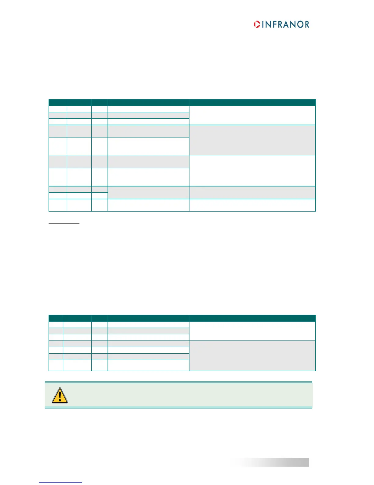
3.9 - POWER CONNECTORS: X9 AND X10
3.9.1 - XtrapulsPac 230 V: X9
Manufacturer: Weidmüller
Type: BLZ 5.08 / 10
Reference: 152956
Tightening torque: 0.4 to 0.5 Nm
- PE connection on the bottom plate,
- 360° shield connection.
DC bus negative voltage output
For the DC bus paralleling in multi-axis applications
or connection with an external capacitor box (ref.
CAPABOX). The direct connection of external
capacitor is prohibited. See “DC bus interfacing”
application note for more details.
DC bus positive voltage output
Internal 100 / 35 W braking
resistor
- Internal braking resistor: 100 / 35 W max
Connect pins 6 and 7 together with a bridge,
- External braking resistor: Min. value = 50
Connect the external resistor between pins 5 and 7.
Braking transistor output
230 V
AC
single-phase mains input
supply
230 V
AC
single-phase +10 % / -15 %
Fully integrated EMC mains filter.
GND reference of the 230 V
AC
supply cable.
Reference potential of the drive housing.
Connection to this pin is not required.
IMPORTANT
Motor and brake cables must be shielded.
The 360° shield connection must be ensured by metallic collars and connected to the ground reference potential.
The GND wire of the motor cable MUST be connected to the ground screw marked with the ground symbol on the
housing bottom plate.
See section 4.6 for grounding and shielding precautions.
3.9.2 - XtrapulsPac 400 V / 45 A and 100 A: X9
Manufacturer: Phoenix Contact
Type: PC 5/ 7-STCL1-7.62
Reference: 1778117
Tightening torque: 0.7 to 0.8 Nm
- PE connection on the bottom plate,
360° shield connection.
DC bus negative voltage output
Input/Output to power drives.
Recommended wire section:
- AWG12 / 105°C for Pac 400 V / 45 A
- AWG10 / 105°C for Pac 400 V / 100 A
Maximum length between two devices: 200 mm
DC bus positive voltage output
DC bus positive voltage output
DC bus negative voltage output
The DC+/DC- polarity between the multi-axis power supply unit and the drives MUST be observed.
 Loading...

