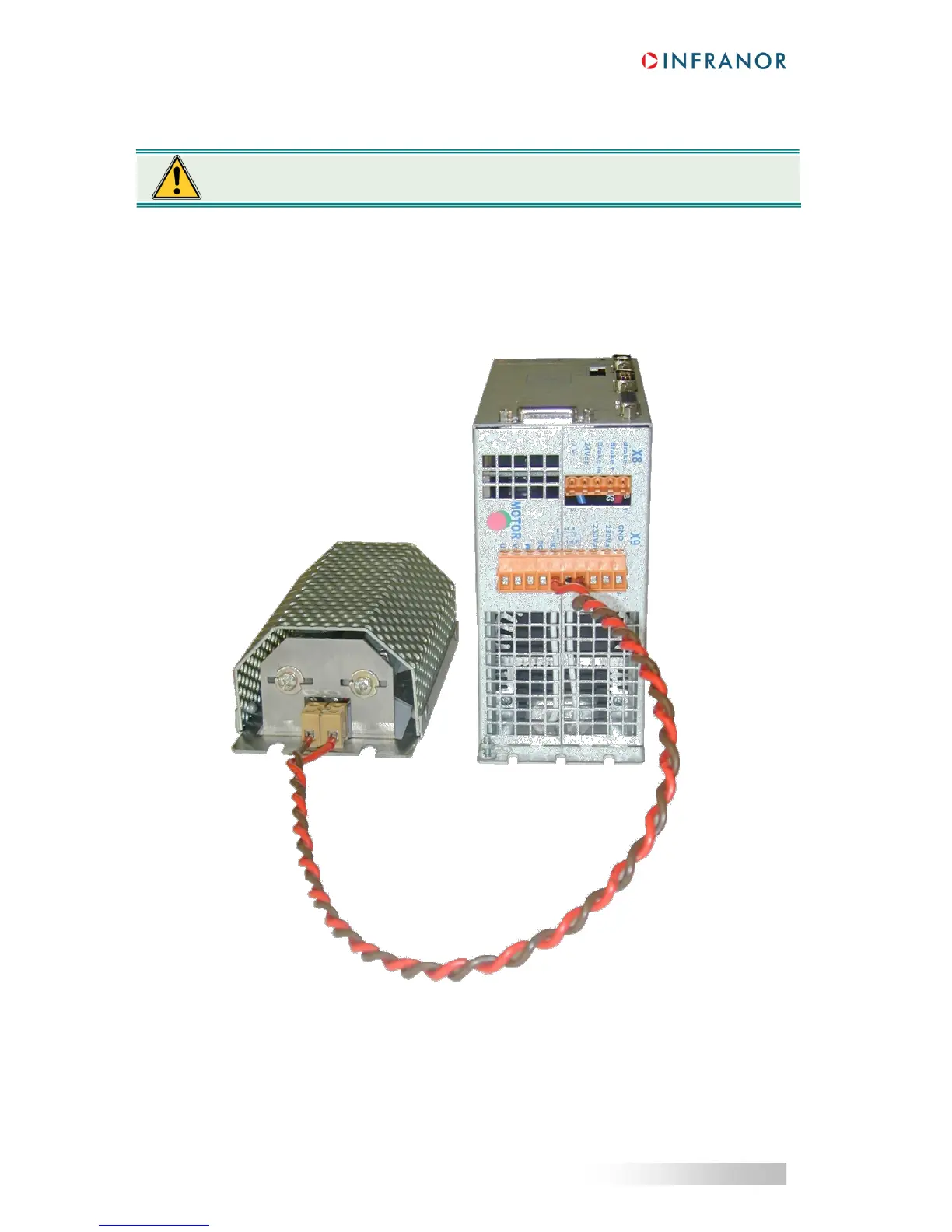
4.4.2 - Connection of the external braking resistor
In order to avoid any EMC or electrical problem, some rules must be observed:
heat must be evacuated,
shielded cables or at least twisted wires must be used,
wires must bear high voltage and high temperature (recommended type: UL1015, AWG 14)
wires must be as short as possible (max. 1 m).
The external braking resistor must be connected between pins 5 and 7 of X9.
Its connection requires the inhibition of the internal braking resistor (removal of the wiring bridge between pins 6
and 7 of X9).
The braking resistor MUST be mounted out of range of heat sensitive and inflammable parts
(plastic, cable sleeves, etc.).
 Loading...

