Chapter 3 – Inputs-Outputs
XtrapulsPac Installation Guide
3.4 - INPUTS-OUTPUTS CONNECTOR: X2
SUB D 26 PIN MALE HD CONNECTOR
Differential input +/-10 V *
Non differential analog input nr. 2
Direct input +/-10 V / GND reference
OptoMos relay: high output impedance if fault
Umax = 50 V, Imax = 300 mA
Polarity must be observed:
AOK+ = positive potential
AOK- = negative potential
External supply for Hall effect sensor,
Hiperface® encoder, SinCos tracks sensor or
digital multi-turn encoders.
External supply: max. 24 V
DC
/ max. 300 mA
Non optocoupled DRIVER PNP "high side" logic
outputs 24 V / 300 mA
Differential encoder output Marker Z-
Differential encoder outputs available on the
XtrapulsPac-ak version only.
5 V / 60 mA via channels A, B, Z
Differential encoder output Marker Z+
Differential encoder output channel B-
Differential encoder output channel B+
Differential encoder output channel A-
Differential encoder output channel A+
All logic inputs are optocoupled
EGND = optocoupled input reference
Vin voltage = 18 V < Vin <27 V
Input impedance Zin = 5 kOhms
Turn-on delay = 20 µs (**)
Turn-off delay = 15 µs (**)
IN5 / PULSE (stepper motor emulation)
IN3 / DIR (stepper motor emulation)
Analog output 2.5 V +/- 2 V - 8 bits. Software
configurable analog output
(*) For a non-differential input signal, ANA1- (pin 10) must be connected to GND (pin 2) on the drive side.
(**) For drives with serial number < 108210001: Zin = 2 kOhm, Turn-on delay = 2 µs, Turn-off delay = 40 µs.
NOTE: IN5 and IN3 inputs can be used as PULSE and DIRECTION logic inputs for stepper motor emulation with
optocoupled 24 V interface.
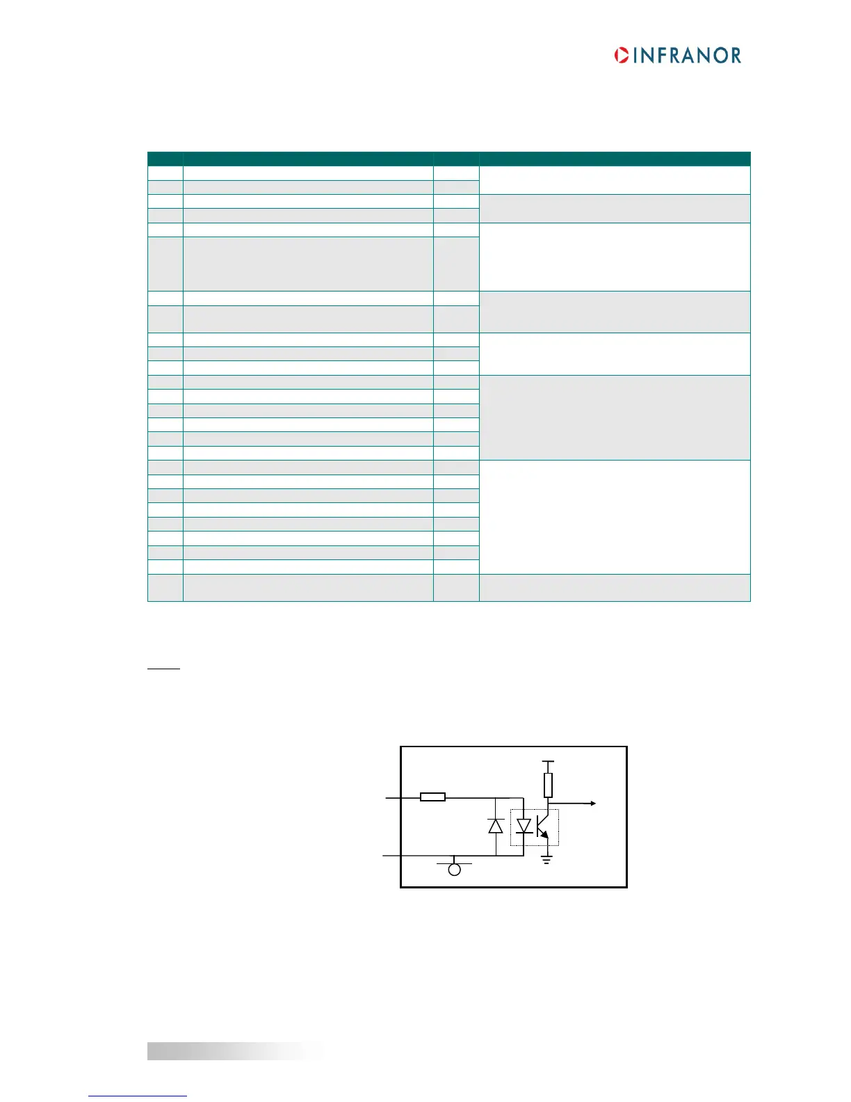
3.4.1 - Specification of the logic inputs
(*) For drives with serial number < 108210001: Zin = 2 kOhm
These optocoupled inputs are working in positive logic.
The input voltage corresponding to level 1 must be between 18 V and 27 V.
 Loading...

