Chapter 3 – Inputs-Outputs
XtrapulsPac Installation Guide
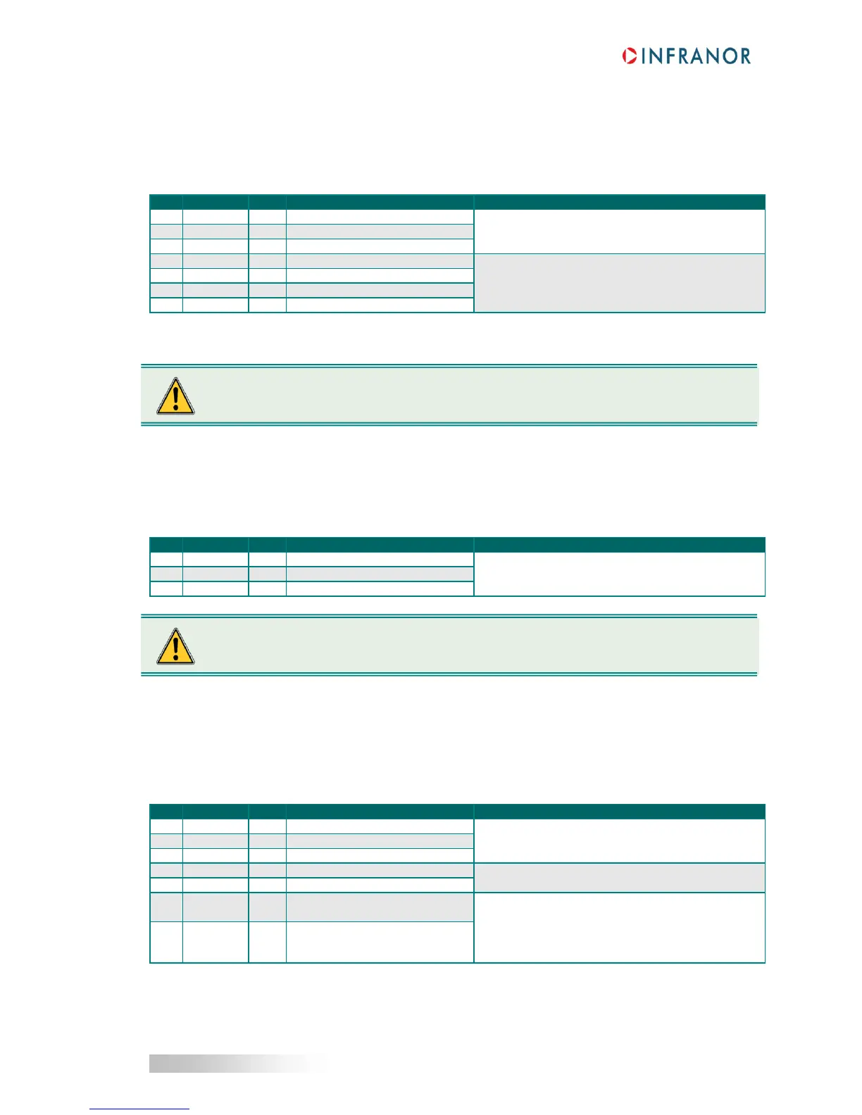
3.9.3 - XtrapulsPac 400 V / 200 A: X9
Manufacturer: Phoenix Contact
Type: PC 16/7-STF-10.16
Reference: 1967508
Tightening torque: 1.7 to 1.8 Nm
- PE connection on the bottom plate,
360° shield connection.
DC bus negative voltage output
Input/Output to power drives.
Recommended wire section:
- AWG 08 / 105°C for Pac 400 V / 200 A *)
Maximum length between two devices: 200 mm
DC bus positive voltage output
DC bus positive voltage output
DC bus negative voltage output
*) According to actual power, use all four DC bus outputs in order to observe the wire section requirements.
3.9.4 - XtrapulsPac 400 V / 08 A and 20 A: X10
Manufacturer: Weidmüller
Type: BLZ 7.62 / 3
Reference: 162339
Tightening torque: 0.4 to 0.5 Nm
Three-phase mains inputs: 400 to 480 V
AC
+10 % /
- 15 %.
Fully integrated EMC mains filter.
3.9.5 - XtrapulsPac 400 V / 08 A and 20 A: X9
Manufacturer: Weidmüller
Type: BLZ 7.62 / 7
Reference: 162343
Tightening torque: 0.4 to 0.5 Nm
Shielded motor cable:
- PE connection on the bottom plate,
- 360° shield connection.
DC bus negative voltage output
For the DC bus paralleling in multi-axis applications.
DC bus positive voltage output
Connection of the internal
400 / 35 W braking resistor
Two possible wirings:
- Internal braking resistor: 400 / 35 W max.
Connect pins 6 an 7 together by a bridge,
- External braking resistor: see section 2.1.2
Connect the external resistor between pins 5 and 7.
Connection to the braking
transistor
Even if the drive is powered via DC+ and DC- signals, the mobile part of X10 must always be
The DC+/DC- polarity between the multi-axis power supply unit and the drives MUST be observed.
 Loading...

