5.3.2 - Integration recommendations
In order to maximize the lifetime of internal components of the XtrapulsPac drive and external electromechanical
components, it is necessary to switch on only when the soft start system is enabled ("Undervoltage" fault
displayed).
Details:
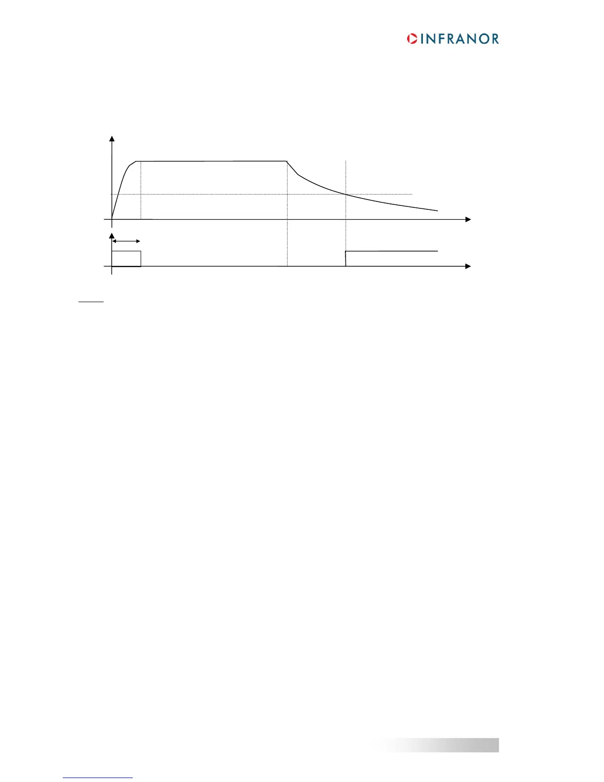
- At t0, the power supply of the drive is switched on. DC bus capacitors are charged via the soft start system.
- After a delay of 2 s at t1, the soft start system is disabled, and the "Undervoltage" fault goes off. The drive is
ready to switch on.
- Between t1 and t2, normal operations are performed by the drive.
- At t2, the drive power supply is switched off. The drive remains operational while the DC bus voltage is higher
than the undervoltage threshold.
- The delay between t2 and t3 is much depending on the application (drive on/off, positive/negative motor
power).
- At t3, the DC bus voltage becomes lower than the undervoltage threshold. The "Undervoltage" fault is
displayed, the drive is disabled and the soft start system is enabled.
5.4 - SIZING OF THE BRAKING SYSTEM
5.4.1 - Introduction
The braking I²t function defines the maximum allowable duty cycle of the braking transistor.
When working with the internal braking resistor, the maximum continuous power must be limited at 35
W.
It can be performed by selecting "Internal braking resistor" in the "Power supply parameters" windows of the Gem
Drive Studio software.
5.4.2 - Method for the design of the braking system
Two different quantities are necessary to completely define an application:
- The peak power:
o It defines the deceleration energy,
o It is limited by the braking transistor current.
- The average power:
o It defines the heat dissipation
 Loading...

