Chapter 5 Function Code Table
- 61 -
Function
Code
Parameter Name Function Description Setting Range Default
b3.27
AI2 min. input For the function and use, see the descriptions of
b3.22 to b3.26.
0.00 V to
b3.29
0.00 V
b3.28 Corresponding setting
of AI2 min. input
0.0% to
100.0%
0.0%
b3.29 AI2 max. input b3.27 to 10.00
V
10.00 V
b3.30 Corresponding setting
of AI2 max. input
0.0% to 100% 100.0%
b3.31 AI2 lter time 0.00s to
10.00s
0.10s
b3.43 AO1 zero offset
coefcient
These two parameters are used to correct the zero
offset of analog output and the output amplitude
deviation. They can also be used to dene the
desired AO curve.
If "b" represents zero offset, "k" represents gain,
"Y" represents actual output, and "X" represents
standard output, the actual output is: Y = kX + b.
The zero offset coefcient 100% of AO1 and AO2
corresponds to 10 V (or 20 mA). The standard
output refers to the value corresponding to the
analog output of 0 to 10 V (or 0 to 20 mA) with no
zero offset or gain adjustment.
For example, if the analog output is used as the
frequency reference, it is expected that the output
is 8 V when the frequency is 0 V, and the output is
3 V at the max. frequency. You need to set the gain
to -0.50 and the zero offset to 80%.
-100.0% to
100.0%
0.0%
b3.44 AO1 gain -10.00 to 10.00 1.00
b3.45 AO2 zero offset
coefcient
-100.0% to
100.0%
0.0%
b3.46 AO2 gain -10.00 to 10.00 1.00
Group b4: Ramp Parameters
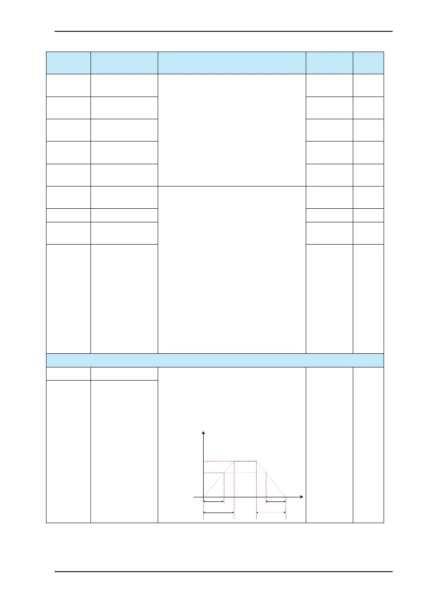
b4.00 Acceleration time Acceleration time indicates the time required for the
AC drive to accelerate from 0 to the rated frequency
(A0.04), shown as t1 in the following gure.
Deceleration time indicates the time required for
the AC drive to decelerate from the rated frequency
(A0.04) to 0, shown as t2 in the following gure.
Output
frequency Hz
Rated frequency
Frequency reference
t1 t2
Time (t)
Actual
acceleration time
Actual
deceleration time
0.1s to 600.0s 3.0s
b4.01 Deceleration time
 Loading...


