Chapter 6 EMC
- 99 -
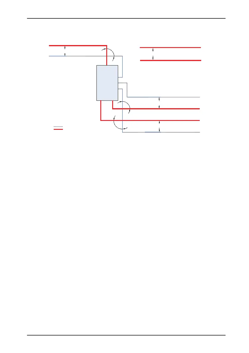
Figure 6-4 Cabling diagram
CS200
Min. 200 mm
Min. 300 mm
Power cable
Motor cable
Min. 500 mm
Min. 500 mm
Braking resistor cable
Motor cable
Power cable
90°
90°
90°
Control cable
Control cable
Power cable
Control cable
Control cable
6.5 Solutions to Current Leakage
•
The AC drive outputs high-speed pulse voltage, producing high-frequency leakage current during the drive
running. To prevent electric shock and even a fire caused by current leakage, it is necessary to install a
residual current circuit-breaker to the AC drive.
•
Each AC drive produces more than 100 mA leakage current. Therefore, the sensitivity current of the residual
current circuit-breaker must be above 100 mA.
•
High-frequency pulse interference may cause the circuit-breaker to malfunction, and thus you must select
residual current circuit-breaker with the high-frequency ltering function.
•
If multiple AC drives are required, each AC drive must be installed with a circuit-breaker.
•
The factors that inuence the leakage current are as follows:
-
AC drive capacity
-
Carrier frequency
-
Type and length of the motor cable
-
EMI lter
•
When the leakage current causes the circuit-breaker to act, you should:
-
Increase the sensitivity current of the circuit-breaker.
-
Replace the circuit-breaker with a new one with high-frequency suppression function.
-
Reduce the carrier frequency.
-
Shorten the length of the output cable.
-
Install a current leakage suppression device.
-
Select a proper EMC lter to suppress the leakage current. For details, see the section 6.3.1 Installation
of the EMC Input Filter on Power Input Side.
 Loading...


