consideration.
2. Install the AC drive upright to facilitate heat dissipation. If multiple braking units are
installed in the cabinet, install them side by side. If one row of braking units need to be
installed above another row, install an insulation guide plate, as shown in Figure 3-2.
3. Use the incombustible material for the installation support.
4. Install the heatsink outside the cabinet in scenarios with heavy metal powder. Ensure
that the full-closed cabinet has sufficient space.
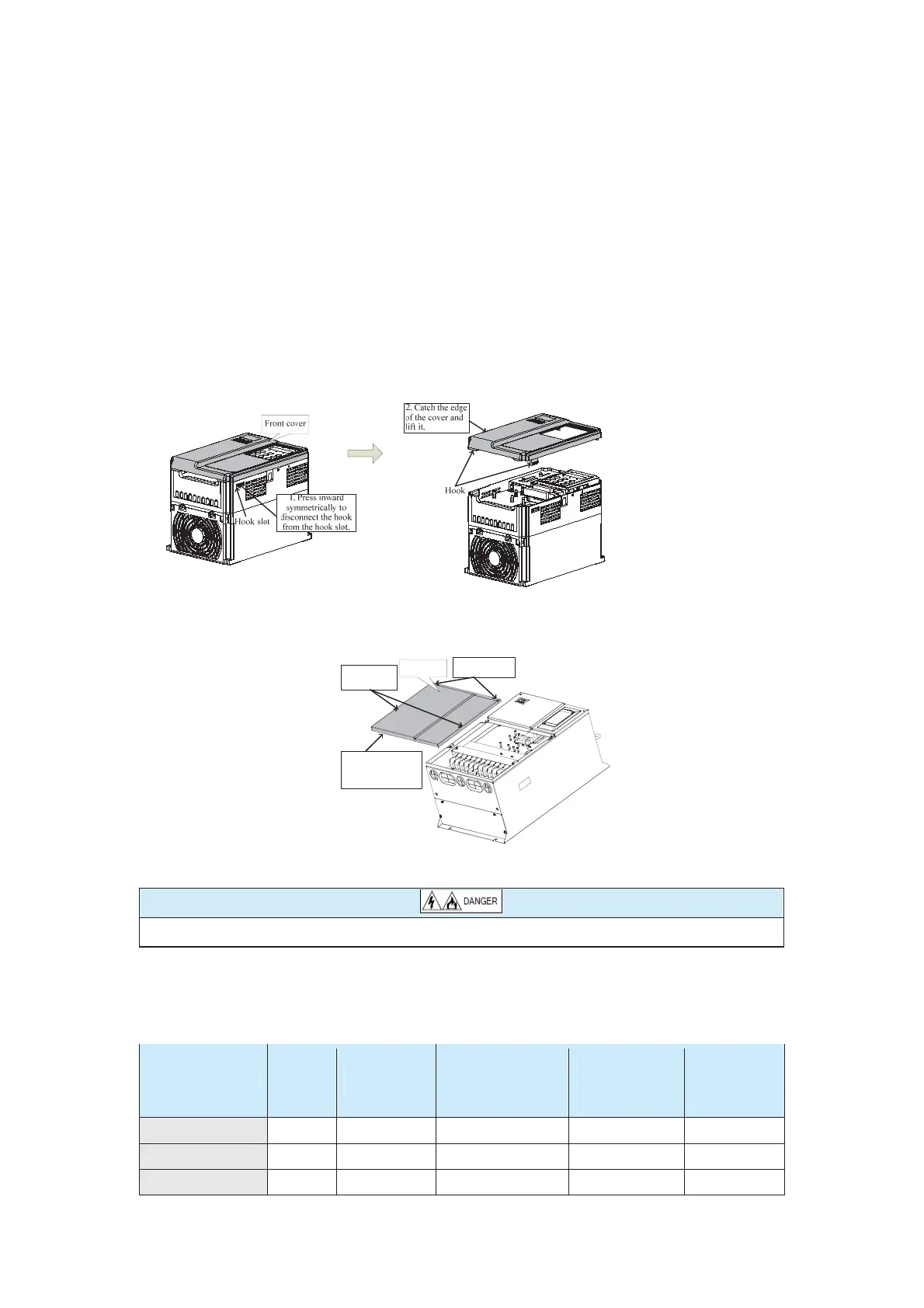
3.1.4 Removal and Installation of the Front Cover
The CS500-4T0.7GB to CS500-4T15GB use the plastic housing, and the
CS500-4T18.5GB and above use the sheet metal housing. The following figures show the
procedure of removing the plastic housing and the sheet metal housing.
Figure 3-3 Operation of removing the plastic housing
Use the tool to press inward so that the hooks of the front cover get out from the hook slot.
Figure 3-4 Operation of removing the sheet metal housing
Front cover
1. Loosen two
screws.
3. Lift the lower
edge of the cover
and remove the
cover
2. Remove the
two screws.
Use the tool to loosen the screws of the front cover.
Prevent the front cover from falling and causing equipment damage and personal injury.
3.2 Electrical Installation
3.2.1 Selection of Peripheral Electrical Devices
Table 3-2 Selection of peripheral electrical devices
CS500 Model
MCCB
(A)
Contactor
(A)
Cable of Input
Side Main Circuit
(mm
2
)
Cable of
Output Side
Main Circuit
(mm
2
)
Cable of
Control
Circuit
(mm
2
)
CS500-4T0.7GB 10 10 2.5 2.5 1.0
CS500-4T1.5GB 16 10 2.5 2.5 1.0
CS500-4T2.2GB 16 10 2.5 2.5 1.0
efesotomas
on.com

 Loading...


