The hundred's digit in the value of F5-08 indicates whether AO2 is used for digital output.
If the hundred's digit is set to 1, it indicates that the relay card CS70RC1 is used and
parameter F5-08 controls relay K1. The ten's digit and unit's digit in the value of F5-08
together indicate the output function selection (same as the function of other relays) of
relay K1. If the hundred's digit is set to 0, it indicates that AO2 is used for analog output.
The AO standard output (offset is 0, gain is 1) is 0
–20 mA or 0–10 V. The FMP output
range is 0 Hz to the setting of F5-09.
The relationship between pulse or analog output and corresponding range is listed in the
following table.
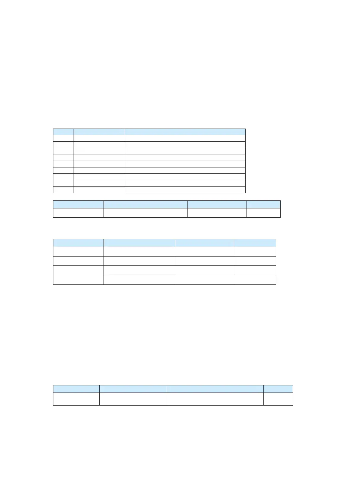
Table 6-4 Relationship between pulse or analog output and corresponding range
Value Function Range
0 Running frequency 0 to maximum output frequency
1 Set frequency 0 to maximum output frequency
2 Output current 0 to 2 times of rated motor current
3 Output torque 0 to 2 times of rated motor torque
4 Output power 0 to 2 times of rated power
5 Output voltage 0 to 1.2 times of rated CS500 voltage
7 AI1 0–10 V
8 AI2 0–10 V (or 0–20 mA)
9 AI3 0–10 V
Function Code Name Setting Range Default
F5-09
Maximum FMP output frequency
0.01–100.00 kHz 50.00 kHz
If the FM terminal is used for pulse output, this parameter is used to set the maximum
frequency of pulse output.
Function Code Parameter Name Setting Range Default
F5-10 AO1 offset coefficient
-100.0%–100.0% 0.0%
F5-11 AO1 gain
-10.00–10.00 1.00
F5-12 AO2 offset coefficient
-100.0%–100.0% 0.00%
F5-13 AO2 gain
-10.00–10.00 1.00
These parameters are used to correct the zero drift of the analog output and the output
amplitude deviation. It can also be used to define any desired AO curve.
If "b" represents zero offset, "k" represents gain, "Y" represents actual output, and "X"
represents standard output, the actual output is: Y = kX + b.
The 100% of AO1 and AO2 zero offset coefficients corresponds to 10 V or 20 mA.
Standard output refers to 0 to maximum analog output, which corresponds to the output of
0
–10 V (or 0–20 mA).
For example, if the analog output is the running frequency and it is expected to output 8 V
when the frequency is 0, and output 3 V at the maximum frequency, the gain shall be set
to -0.50, and the zero offset shall be set to 80%.
Group F6: Auxiliary Functions 1
Function Code Parameter Name Setting Range Default
F6-07
Acceleration/Deceleration
mode
0: Linear acceleration/deceleration
1: S-curve acceleration/deceleration
0
It is used to select the frequency change mode during the AC drive start/stop process.
z 0: Linear acceleration/deceleration
The output frequency increases or decreases in linear mode. The CS500 provides
two groups of acceleration/deceleration time. The acceleration/deceleration time can
be selected via a multifunctional DI terminal.
efesotomas
on.com

 Loading...


