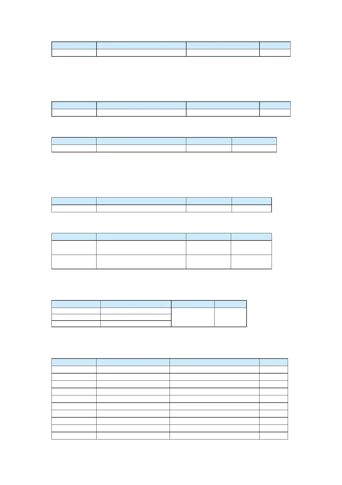
Function Code Parameter Name Setting Range Default
F9-03 Over-voltage stall gain 0 (no stall overvoltage) to100 0
It is used to adjust the AC drive’s capacity in suppressing the over-voltage stall. The larger
the value is, the higher the suppressing capacity is.
For small-inertia load, the value must be small. Otherwise, the dynamic response of the
system will be slow. For large-inertia load, the value must be large. Otherwise, the
suppressing result will be poor, probably resulting in overvoltage.
Function Code Parameter Name Setting Range Default
F9-04 Over-voltage stall protection voltage 120%–150% 130%
It is used to set the threshold of the overvoltage stall protection function. Once the
threshold is exceeded, the AC drive performs the protective function.
Function Code Parameter Name Setting Range Default
F9-05 Over-current stall gain 0–100 20
It is used to adjust the AC drive’s capacity in suppressing the over-current stall. The larger
the value is, the higher the suppressing capacity is.
For small-inertia load, the value must be small. Otherwise, the dynamic response of the
system will be slow. For large-inertia load, the value must be large. Otherwise, the
suppressing result will be poor and over-current fault may occur.
Function Code Parameter Name Setting Range Default
F9-06 Over-current stall protection current 100%–200% 150%
It is used to set the threshold of the over-current stall protection function. Once the
threshold is exceeded, the AC drive performs the protective function.
Function Code Name Setting Range Default
F9-12
Input phase loss protection
0: Disabled
1: Enabled
1
F9-13
Output phase loss protection
0: Disabled
1: Enabled
1
F9-12 is used to set whether to perform protection in the case of input phase loss. Only
the CS500-4T18.5GB and above power rating provide the protection function.
F9-13 is used to set whether to perform protection in the case of output phase loss.
Function Code Parameter Name Setting Range Default
F9-14 1st fault type
F9-15 2nd
fault type
F9-16 Latest fault type
0–99 /
It is used to record the types of the latest three faults on the AC drive. The value 0
indicates no fault, while 1 to 99 indicates ERR01 to ERR99. For details, see Chapter 8.
Group FA: Crane Time Sequence Functions
Function Code Parameter Name Setting Range Default
FA-00
FWD startup frequency 1
0.00–50.00 Hz 2.00 Hz
FA-01
REV startup frequency 1
0.00–50.00 Hz 2.00 Hz
FA-02
FWD brake release current 1
0.0%–100.0% (rated motor current) 30.0%
FA-03
REV brake release current 1
0.0%–100.0% (rated motor current) 30.0%
FA-04
Brake release time 1 0.0–10.0s 0.5s
FA-05
Brake apply frequency 1 0.00–50.00 Hz 2.00 Hz
FA-06
Brake apply time 1 0.0–10.0s 0.5s
FA-08
DC braking current 0%–100% 0%
FA-10
DC braking output time 0.0–10.0s 0.0s
FA-11
DC braking waiting time 0.0–10.0s 0.0s
efesotomas
on.com

 Loading...


