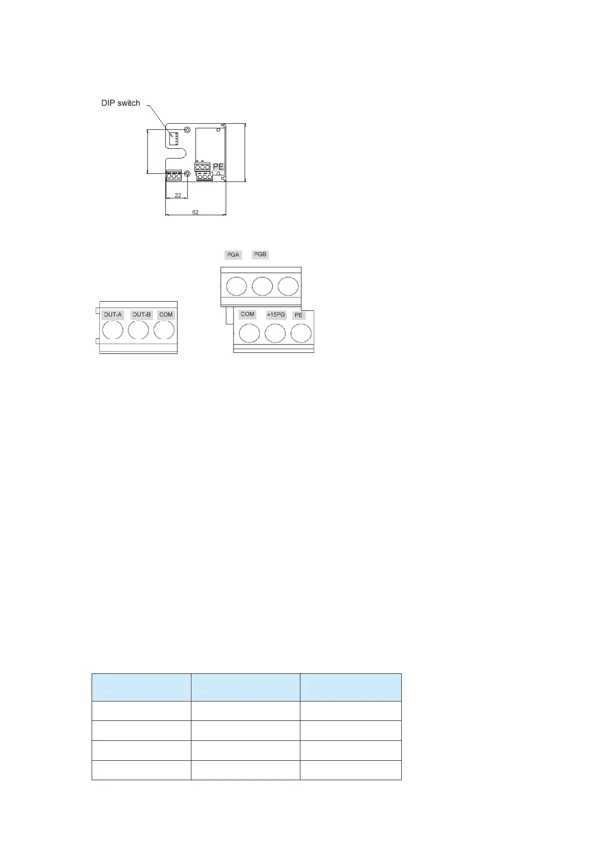
Figure A-2 Size of the PG card
60
45
Figure A-3 Terminals of the PG card
A.2 Usage Description
Function
A PG card is required when CLVC is adopted. A standard PG card includes the circuit for
processing two-channel orthogonal signals of the encoder (open-collector ouput or
push-pull output encoders) and the +15 V power supply. An enhanced PG card can also
perform frequency division on the encoder signals. Select a proper PG card based on
actual requirements.
Terminals and DIP Switches
A PG card provides 9 wiring terminals, as shown in A.1. The terminals +15PG and COM
output power supply to the encoder. PGA and PGB are encoder signal input terminals.
OUT-A, OUT-B, and COM are frequency-division signal output terminals. PE is the
shielded cable wiring terminal (PE is not grounded, and you can ground it when using the
PG card).
For the PG card with the frequency division function, the frequency division coefficient is
determined by the DIP switch. The frequency division coefficient is the binary number
expressed by the 5-bit DIP switch multiplied by 2. The single switch marked with 1 is the
low bit, and the single switch marked with 5 is the high bit. In ON state, a switch is valid,
expressed by 1; in OFF state, a switch is invalid, expressed by 0. The frequency division
coefficients are listed in the following table.
Table A-3 Frequency division coefficients
Binary Number
Frequency Division
Coefficient
0 00000 No output
1 00001 No output
2 00010 2 x 2
… … …
efesotomas
on.com

 Loading...


