i … i x 2
31 11111 31 x 2
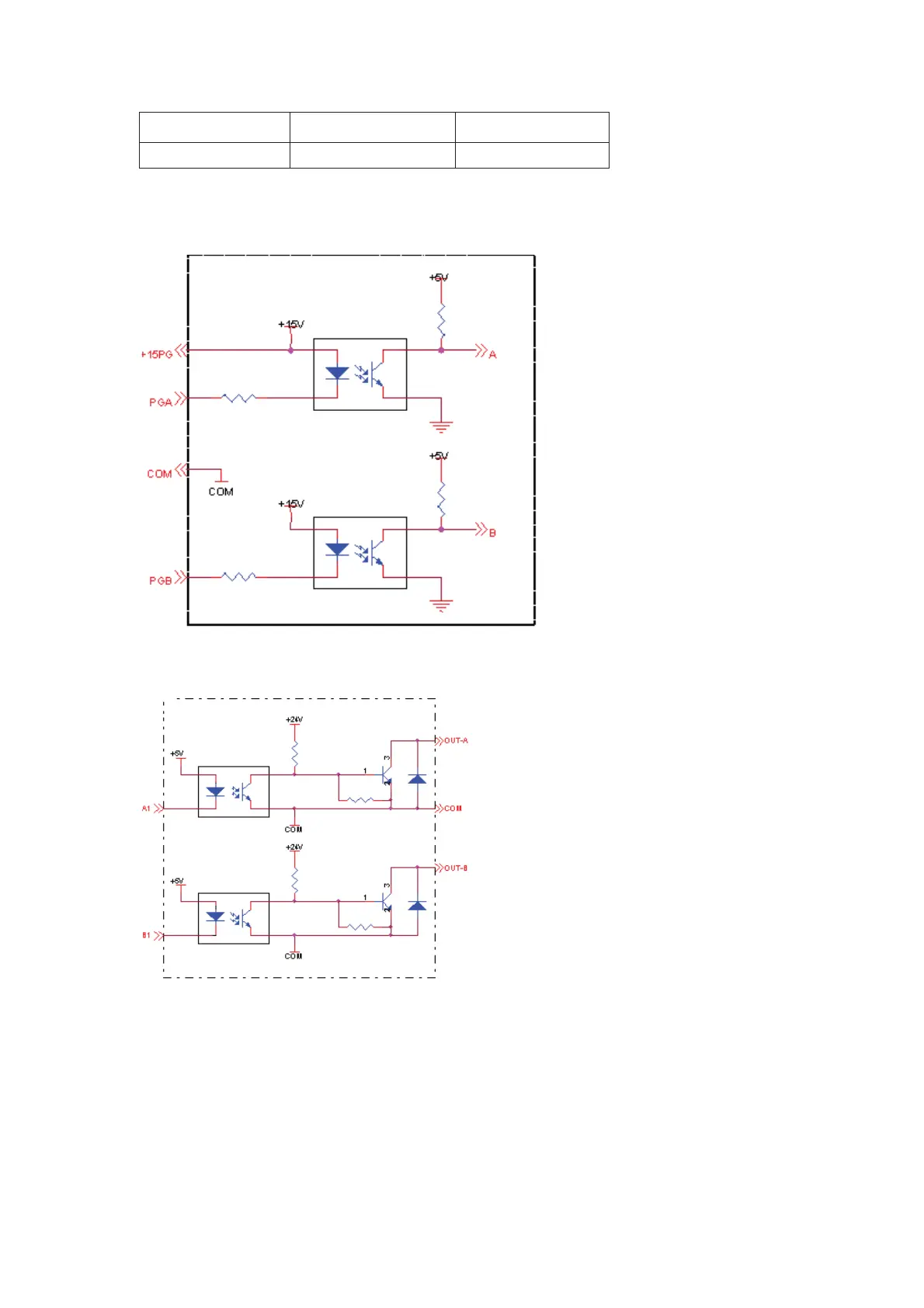
Principle Diagram
Figure A-4 Interfaces of the encoder
Figure A-5 Frequency division interfaces
Note:
1. The signal cable of the PG card and the power cable must be laid separately. Parallel
cabling is forbidden.
2. Use a shielded cable as the signal cable of the PG card to prevent interference to
encoder signals.
3. The shielding layer of the shielded cable must be grounded on one end (not both ends,
such as PE) to prevent interference to encoder signals.
4. The length of the shielded cable must be less than 80 m.
efesotomas
on.com

 Loading...


