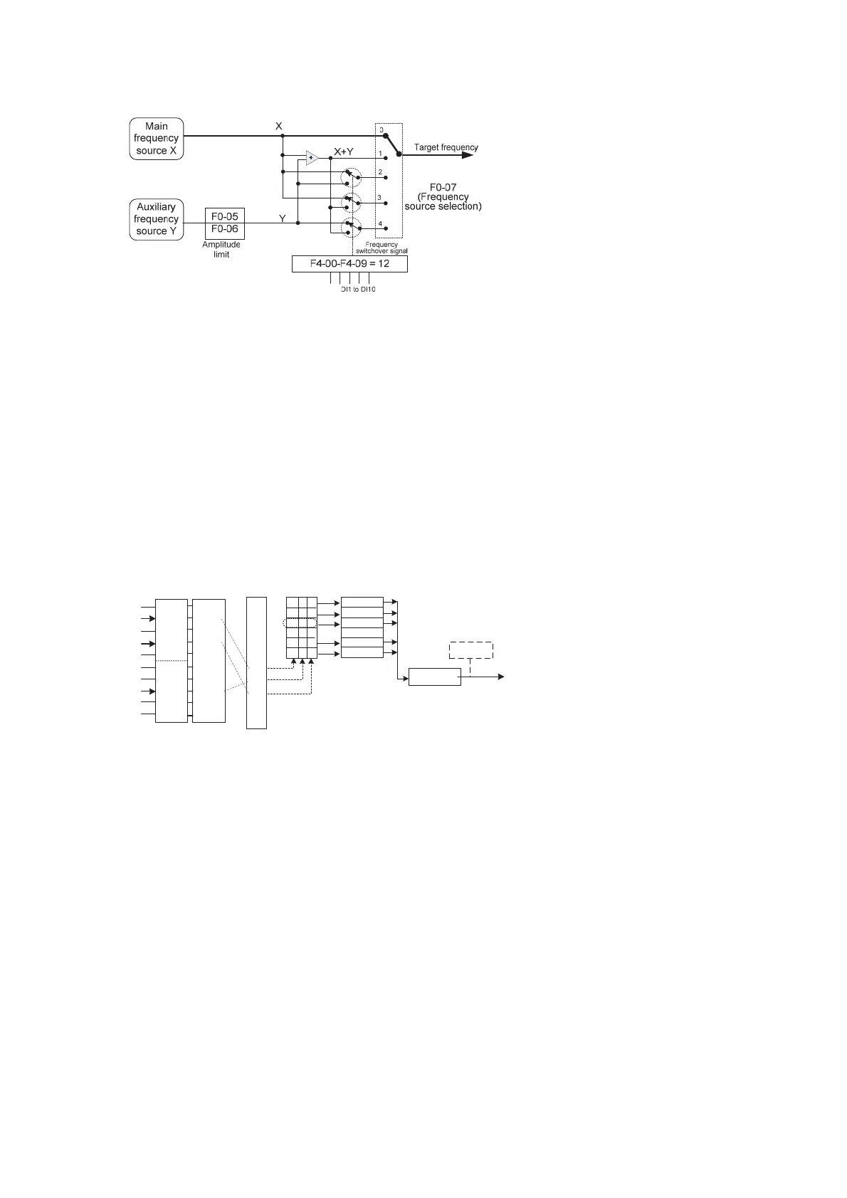
Superposition of the main and auxiliary frequency sources is used in CLVC scenarios. For
example, using the malin frequency source for setting the required frequency and the
auxiliary frequency soure for automatic adjustment, in conjunction with switchover
performed by the external DI terminal signal, the required CLVC can be implemented.
4.5.3 Frequency Setting in the Multi-Speed Mode
The multi-speed mode can be used to set the target running frequency if the running
frequency of the AC drive need not be ajusted continuously and only several frequency
values are required. The CS500 supports a maximum of eight speeds, which can be set
by combinations of the status of of three DI terminals. Set the values of the DI terminals to
12 to 14 to specify the input interfaces of the multi-speed commands. The multiple speeds
are set based on the multi-speed table in Group FC. The prerequisite is to set F0-03 to 6,
as shown in the following figure.
Figure 4-10 Frequency set in multi-speed mode
F4-00
F4-01
F4-02
F4-03
F4-04
F4-05
F4-06
F4-07
F4-08
F4-09
.
.
.
.
.
14
13
12
.
..
0 0 0
0 0 1
0 1 0
. .
1 1 0
1 1 1
FC-00
FC-01
FC-02
..
FC-06
FC-07
F0-03 = 6
F0-07 = 0
Target running
frequency
0
1
Terminal
Function
code
Value
Status
combination
Multi-frequency
segment
Main frequency
source X
DI1
DI2
DI3
DI4
DI5
DI6
DI7
DI8
DI9
DI10
0
(Binary)
Use "Multi-speed" as the
frequency source
In the preceding figure, DI2, DI4, and DI8 are selected as the input interfaces of
multi-speed signals. Based on the status combination of corresponding three binary
values, multi-speed is selected. When (DI2, DI8, DI4) = ( 0, 1, 0), the status combination
value is 2, indicating that the frequency value set in FC-02 is selected. In addition, F0-03
(Main frequency source X) is set to 6 (Multi-speed), and therefore, the target running
frequency is the value of FC-02.
The CS500 supports a maximum of three DI terminals used as the input interfaces of
multi-speed commands. You can also use less than three DI terminals as the interfaces.
The status value of the empty digit is considered as 0.
4.5.4 Frequency Setting by Analog
The setting for using a potentiometer to adjust the running frequency of the AC drive is
shown in the folloing figure. The output frequency of the AC drive can be adjusted within
the range from zero to the maximum frequency.
Figure 4-11 Frequency set by analog
efesotomas
on.com

 Loading...


