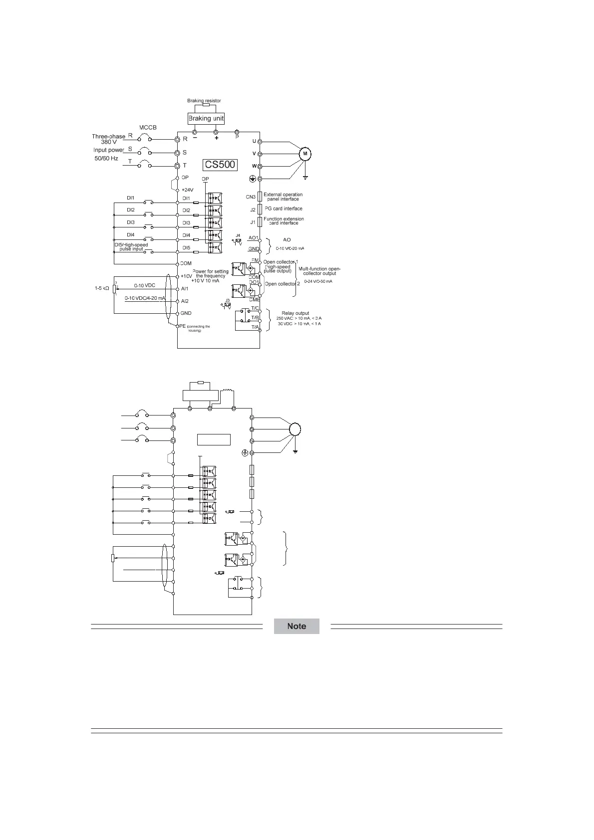
Figure 3-6 Three-phase wiring for the CS500 of 37 kW to 55 kW
Figure 3-7 Three-phase wiring for the CS500 of 75 kW or above
DI1
DI2
DI3
DI4
DI5
COM
W
V
U
–
+
P
+24V
OP
T/C
T/B
T/A
250 VAC: >10 mA, < 3 A
30 VDC: > 10 mA, < 1 A
+10V
AI1
AI2
PE(connecting the
housing)
1
2
3
+10 V 10 mA
0-10 VDC
0-10 VDC/4-20 mA
1-5 kȍ
J3
IV
VI
J4
COM
FM
GND
DO1
CME
AO1
0-10 V/0-20 mA
J1
J2
CN3
0-24 V/0-50 mA
OP
Braking resistor
DI1
DI2
DI3
DI4
DI5/High-speed
pulse input
CS500
Relay output
Power for setting
the frequency
AO
External operation
panel interface
PG card interface
Function extensiion
card interface
Multi-function open-
collector output
Open collector 1
Open collector 2
(high-speed
pulse output)
M
MCCB
T
S
R
T
S
R
Input power
Three-phase
380 V
50/60 Hz
Braking unit
External reactor
GND
z Ƽ indicates the main circuit terminal, and ż indicates the control circuit terminal.
z The models of 30 kW or below have a built-in braking unit as standard, and no external braking unit
is required.
z The models of 7.5 kW to 55 kW have a built-in DC reactor as standard.
z Select a proper braking resistor based on actual requirements. For details, see the preceding
braking resistor selection guideline.
efesotomas
on.com

 Loading...


