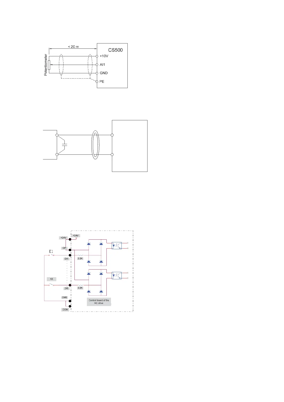
Figure 3-8 Wiring of AI terminals
In certain scenarios where analog signals suffer serious interference, a filter capacitor or
ferrite magenetic core needs to be installed on the analog signal source, as shown in the
following figure.
Figure 3-9 Wiring of AI terminals in special scenarios
AI1
GND
Cross or wind two to three coils
in the same direction
0.022 uF, 50 V
Ferrite
magnetic core
C
CS500
2. Wiring of DI terminals
Generally, shielded cable must be used and the cable length must be less than 20 m.
When active driving is adopted, filtering measures must be necessarily taken to reduce
interference to the power supply. It is recommended to use the contact control mode.
1) Wiring of dry contact common cathode
Figure 3-10 Wiring of dry contact common cathode
This is the most commonly used wiring mode. If external power supply is applied, remove
jumper bars between +24V and OP and between COM and CME, and connect the
positive pole of external power supply to OP and the negative pole to CME.
efesotomas
on.com

 Loading...


