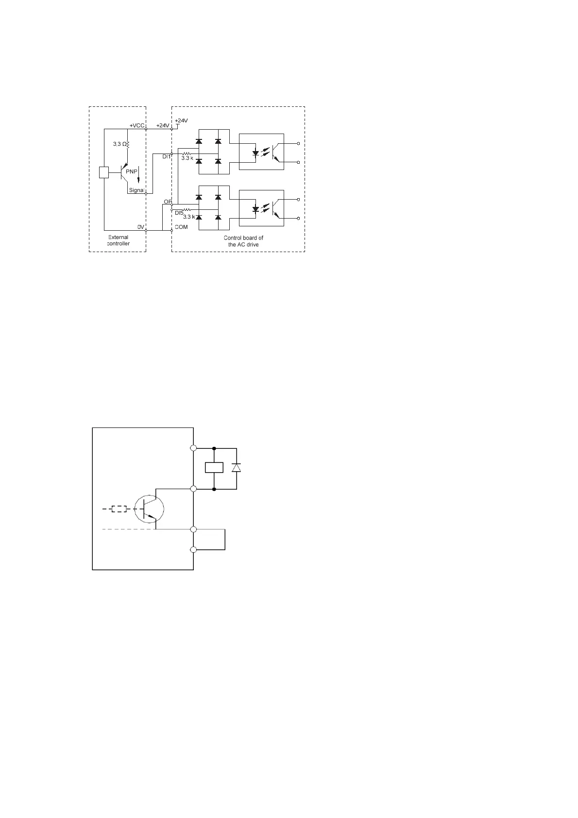
4) Source wiring
Figure 3-13 Source wiring
In such wiring mode, remove the jumper bar between +24V and OP. Connect +24V to the
common port of the external controller and connect OP to COM. If external power supply
is used, remove the jumper bar between CME and COM.
3. Wiring of DO terminals
When the DO terminal needs to drive the relay, an absorption diode must be installed at
two sides of the relay coil. Otherwise, it may cause damage to the 24 VDC power supply.
Do not reverse the polarity of the absorption diode during installation, as shown in the
following figure. Otherwise, the 24 VDC power supply is damaged immediately if there is
digital output.
Figure 3-14 Poliarity installation of the absorption diode
CS500
CME
COM
DO
+24V
efesotomas
on.com

 Loading...


