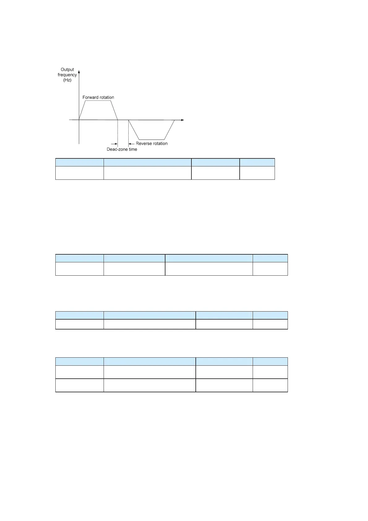
reverse rotation, as shown in the following figure.
Figure 6-5 Dead-zone time
Function Code Parameter Name Setting Range Default
F8-14
Relay card enable/K2 function
selection
0–122
0
This parameter indicates the relay card enable selection when the CS500 is connected to
relay card CS70RC1 and the output function selection of relay K2.
Before connecting the CS500 to CS70RC1, connect jumper J4 across two "320" pins on
the right first and then set the hundred's digit in the value of F8-14 to 1 to enable the relay
card. If either of the preceding two operations is not performed, CS70RC1 cannot be used
properly on the CS500.
The ten's digit and unit's digit in the value of F8-14 determine the K2 output function. K2
provides the same functions as other relays.
Function Code Parameter Name Setting Range Default
F8-16
Over-modulation
enable
0: Over-modulation invalid
1: Over-modulation valid
1
The over-modulation function indicates that the output voltage can be increased by
adjusting the utilization rate of bus voltage when the input voltage is low or the AC drive
works with heavy load for long. If the over-modulation is effective, the harmonics of the
output current increases slightly.
Function Code Parameter Name Setting Range Default
F8-17 Accumulative running time setting
0–65000 h 0 h
It is used to pre-set the AC drive’s accumulative running time. If the accumulative running
time (F7-09) reaches the value of this parameter, the DO terminal outputs a signal
indicating that the set accumulative running time is reached.
Function Code Parameter Name Setting Range Default
F8-19
Frequency detection
value (FDT level)
0.00 Hz to
maximum frequency
50.00 Hz
F8-20
Frequency detection hysteresis
value (FDT hysteresis)
0.0%–100.0% (FDT
level)
5.0%
The two parameters are used to set the detection value of the output frequency and the
hysteresis value after the output is disabled.
The FDT function is shown in the following figure.
efesotomas
on.com

 Loading...


