Electrical Installation
‑180‑
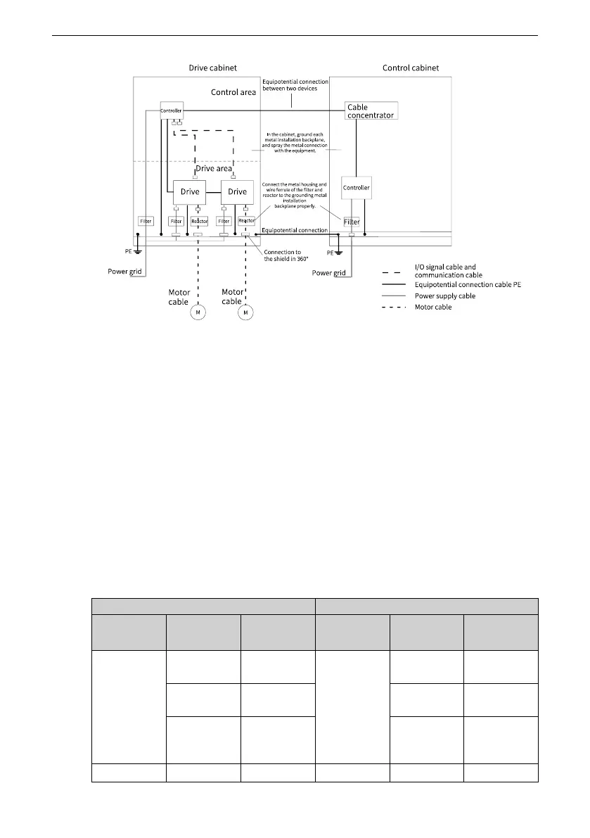
Figure 8‑63 Recommended wiring of the cabinet system
8.6 Communication Connection
8.6.1 RS485 Communication Wiring
RS485 communication connection with PLC
Use a three‑conductor shielded cable for the RS485 bus to connect to the 485+, 485‑,
and CGND terminals of the AC drive. Use the twisted pair cable to connect to the 485+
and 485‑ terminals and use the other cable to connect to the RS485 reference ground
CGND. Connect the shield to the equipment ground. Connect a 120 Ω termination
resistor at each end of the bus to prevent RS‑485 signal reflection. The following table
specifies the cable pin for the communication between the AC drive and PLC.
Table 8–21 Cable pin for communication between the AC drive and PLC
AC Drive
PLC
Communica
tion Type
Signal Name
Function Communica
tion Type
Signal Name
Function
RS485 RS485+
RS485 signal
(positive)
RS485 RS485+
RS485 signal
(positive)
RS485‑
RS485 signal
(negative)
RS485‑
RS485 signal
(negative)
CGND
Signal
reference
ground
CGND
Signal
reference
ground
‑
GND (CGND) Enclosure
‑
GND (CGND) Enclosure

 Loading...


