- 46 -
2 System Commissioning
2
Table 2-1 Judging door open/close limit
Door State State of X3 Signal Indicator State of X5 Signal Indicator
Door open/close limit
signal set to NO
At door open limit Steady ON Steady OFF
During door open/close Steady OFF Steady OFF
At door close limit Steady OFF Steady ON
Door open/close limit
signal set to NC
At door open limit Steady OFF Steady ON
During door open/close Steady ON Steady ON
At door close limit Steady ON Steady OFF
If the states of X3 and X5 signal indicators are inconsistent with the actual door state or keeps
unchanged, check:
a. Whether cable connection between the CTB and the door machine controller is correct
b. Whether the function setting of door open/close output terminals is correct
c. Whether door machine controller commissioning fails. If yes, perform commissioning again.
4. After door machine controller commissioning is completed, check whether the setting of F5-25 Bit2/
Bit4 is consistent with the actual NO/NC feature of door open/close limit signals.
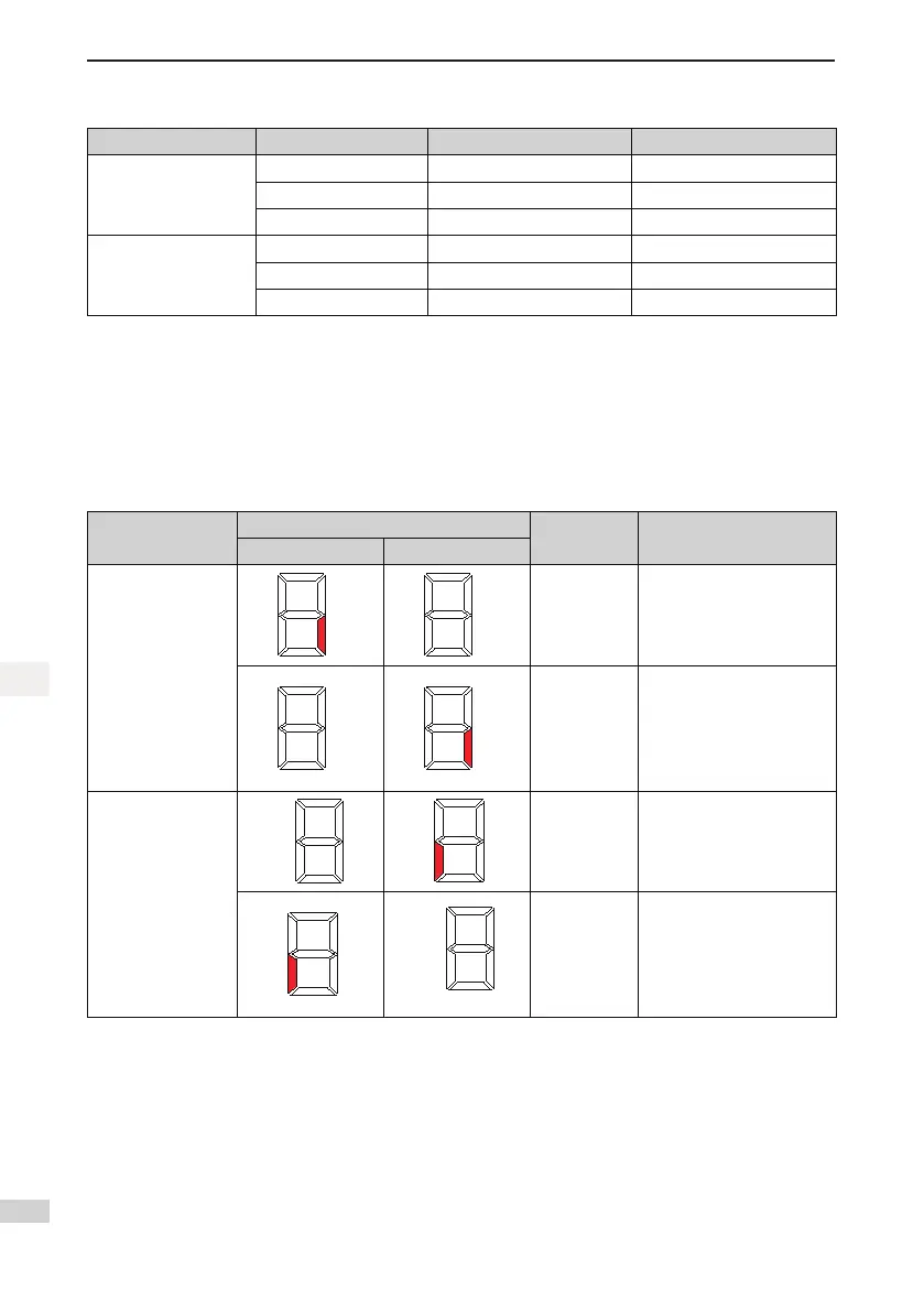
Table 2-2 Checking consistency between F5-25 and actual door open/close limit signals
Signal
Signal State Monitoring
Signal State
Judging
Re-set F5-25 Bit2/Bit4?
At Door Open Limit At Door Close Limit
Door open limit
signal
(Segment C of LED1
in F5-35)
Normal Not required
Abnormal
Set F5-25 Bit2 to the
opposite state:
If the original value is 0,
change it to 1.
If the original value is 1,
change it to 0.
Door close limit
signal
(Segment E of LED1
in F5-35)
Normal Not required
Abnormal
Set of F5-25 Bit4 to the
opposite state:
If the original value is 0,
change it to 1.
If the original value is 1,
change it to 0.
2.2.5 HCB Installation and Setting
This section describes HCB installation and setting of the single-door independent elevator system. Details
on HCB installation setting of parallel elevator system and opposite door elevator system, refer to sections
are not described here.
HCB installation
1. Install an HCB for each service oor (non-service oors do not require the HCB), as shown in Figure
2-5.
 Loading...