- 75 -
3 System Functions
3
Table 3-4 STO pin denitions
Pin Signal Mark Voltage Description
1 STOA 24V1 0 V/24 V STO channel A input
2 GND_STOA COM1 0 V Reference ground of STO channel A input
3 STOB 24V2 0 V/24 V STO channel B input
4 GND_STOB COM2 0 V Reference ground of STO channel A input
5 DNS+ DNS+ 0 V/24 V STO feedback positive
6 DNS- DNS- 0 V STO feedback negative
STOA and STOB are two channels of STO, each of which can stop cabinet output. The dual-channel
redundancy design meets SIL3 safety level.
DNS+ and DNS- are STO feedback, and are connected to the monitor controller for detecting whether the
STO circuit is damaged.
3.5.1 Safety Circuit of 110 V
The STO function takes the place of the RUN contactor, and is wired in the same way as the RUN
contactor. A safety relay is used to adapt the 24 V input of the STO card to the 110 V power of common
safety circuit.
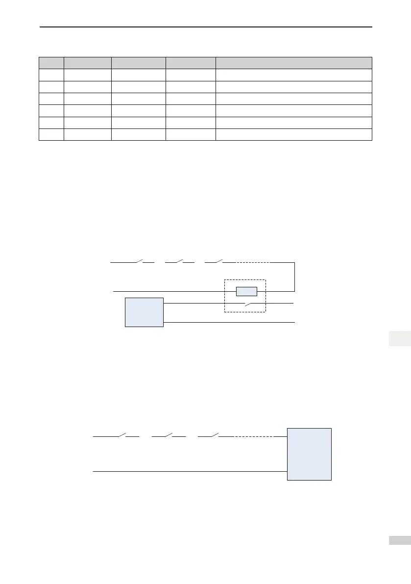
Figure 3-12 STO wiring under 110 V safety circuit
110 V
N
Safety relay
24 V
COM
STO
Safety circuit
The RUN contactor is replaced with a safety relay and a STO card. The feedback terminals DNS+ and
DNS- of the STO card are connected to the DI terminals of the MCB, and the power ows from DNS+ to
DNS- (similar to a single-direction switch).
3.5.2 Safety Circuit of 24 V
If the safety circuit is 24 V, the STO card can be directly connected to the safety circuit, as shown in the
following gure.
Figure 3-13 STO wiring under 24 V safety circuit
The STO card replaces the RUN contactor.
 Loading...