- 32 -
2 System Commissioning
2
2.1.2 Use of the LED Operation Panel
The LED operation panel is connected to the RJ45 interface of the controller by using an 8-core at cable.
You can modify the parameters, monitor the working status and start or stop the controller by operating the
operation panel. The following gure shows the LED operation panel.
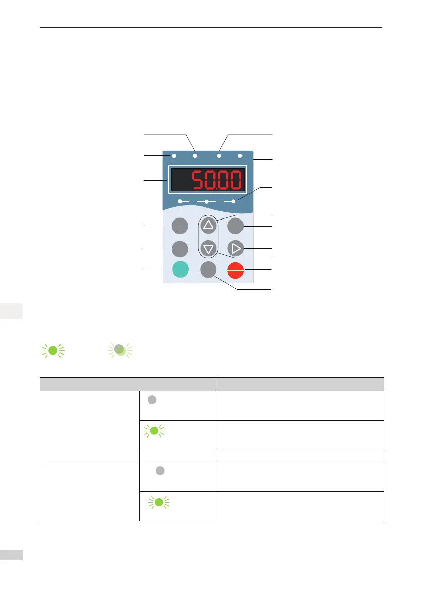
Figure 2-3 Diagram of the LED operation panel
MF.K
RUN
STOP
RES
QUICK
PRG ENTER
RUN
LOCAL/REMOT FWD
/REV TUNE/TC
RPM
%
A VHz
Reserved
RUN indicator
Data display
Programming key
RUN key
Menu key
Up/Down indicator
Auto-tuning indicator
Fault hiding key
Stop/Reset key
Shift key
UP key
Down key
Confirm key
Unit indicator
ON: down direction
OFF: up direction
Function Indicators
: ON, : OFF, : blinking
Indicator Indication
RUN
OFF indicates the STOP status.
ON indicates the RUNNING status.
LOCAL/REMOT - Reserved
FWD/REV
OFF indicates elevator in up direction.
ON indicates elevator in down direction.
 Loading...