- 48 -
2 System Commissioning
2
Performance adjustment of system control
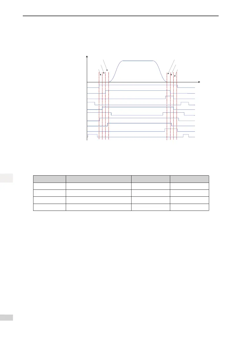
Figure 2-6 Running time sequence
V (speed)
t (time)
F2-16
F3-18
F3-19
F3-20
F8-11
F2-17
RUN contactor
Brake contactor
Shorting door lock circuit contactor
Shorting PMSM stator contactor
Internal running status
Leveling signal
RUN contactor feedback
Brake contactor feedback
Shorting door lock circuit
contactor feedback
Shorting PMSM stator
contactor feedback
1. Riding comfort adjustment at elevator startup and stop
The parameter setting related to riding comfort adjustment at elevator startup and stop is described in
the following table.
Parameter No. Parameter Name Setting Range Default
F2-00 Speed loop proportional gain Kp1 0–100 40
F2-01 Speed loop integral time Ti1 0.01–10.00s 0.60s
F2-03 Speed loop proportional gain Kp2 0–100 35
F2-04 Speed loop integral time Ti2 0.01–10.00s 0.80s
1) Adjustment to abnormal motor startup
F2-00, F2-01, F2-03 and F2-04 are used to adjust the speed dynamic response characteristics
of the motor.
• To achieve a faster system response, increase the proportional gain and reduce the
integral time. However, too large proportional gain or too small integral time may lead to
system oscillation.
• Decreasing the proportional gain and increasing the integral time will slow the dynamic
response of the motor. However, too small proportional gain or too large integral time may
cause motor speed tracking abnormality, resulting in fault E33 or instable leveling at stop.
The default setting is proper for most large-power motors, and you need not modify these
parameters. These parameters need to be adjusted only for small-power motors (P ≤ 5.5 kW)
because they may have oscillation. To eliminate oscillation, do as follows:
Decrease the proportional gain rst (between 10 and 40) to ensure that the system does not
oscillate, and then reduce the integral time (between 0.1 and 0.8) to ensure that the system has
quick response but small overshoot.
 Loading...