Board Information
The board information control displays static information about your board.
• Board Name: Indicates the official name of the board given by the BTS.
• Board Revision: Indicates the revision of the board.
• MAX Version: Indicates the version of the system Intel MAX 10.
JTAG Chain
The JTAG chain control shows all the devices currently in the JTAG chain.
Note: You should place the system Intel MAX 10 and FPGA in the JTAG chain when running
the BTS GUI.
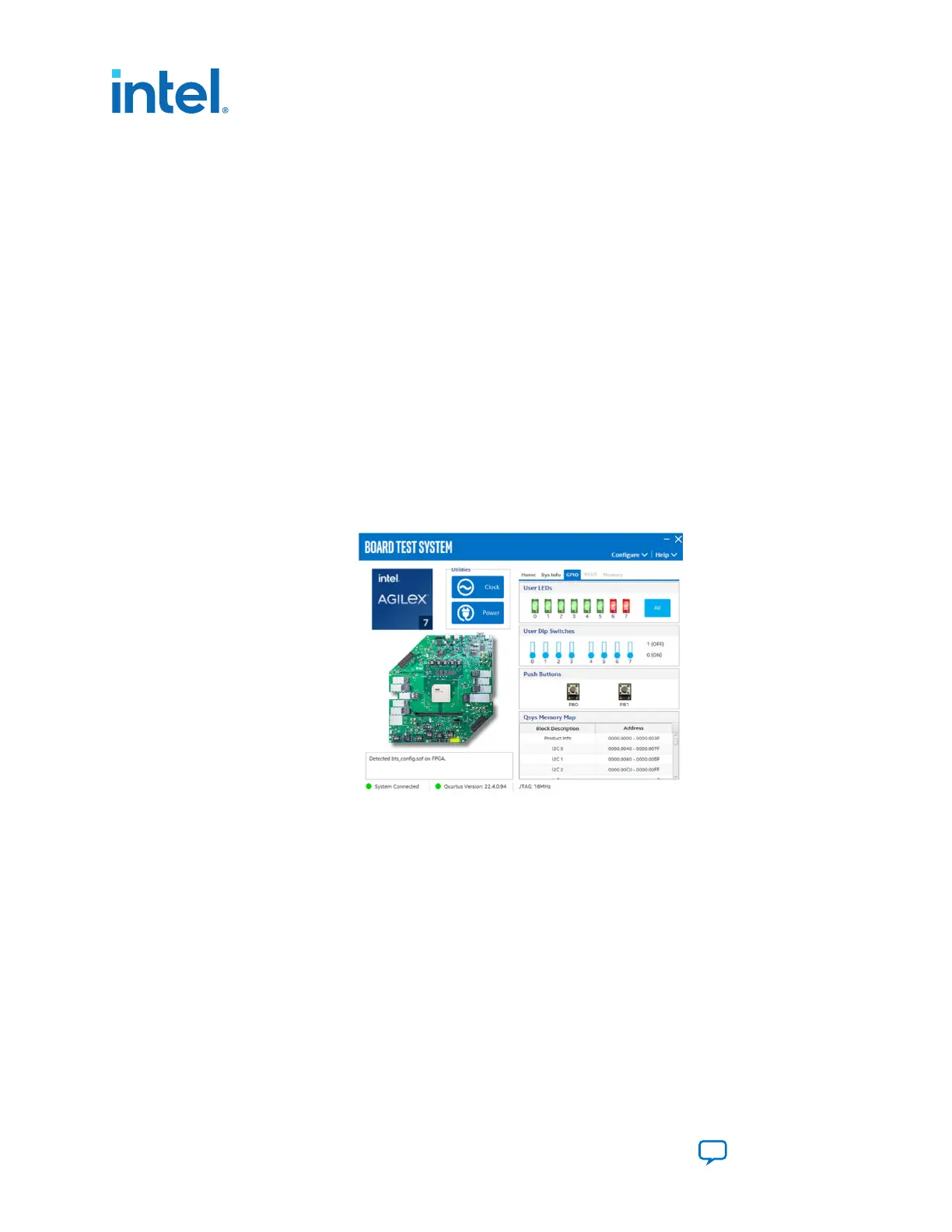
4.2.4. The GPIO Tab
The GPIO tab allows you to interact with all the general-purpose user I/O components
on your board. You can turn LEDs on or off and see the status of push buttons and dip
switches.
Figure 8. The GPIO Tab
The following sections describe the controls on the GPIO tab.
User LEDs
The User LEDs control displays the current state of the user LEDs. Toggle the LED
buttons to turn the board LEDs on and off. Click the All button to reverse the state of
all the LEDs.
User Dip Switches
The User Dip Switches control display the status of the USER_SW[0:3](S1) and
USER_SW[4:7](S6).
Push Buttons
The Push Button control shows the status of PB0(S2) and PB1(S3).
4. Board Test System
776646 | 2023.05.31
Intel Agilex
®
7 FPGA I-Series Transceiver (6 × F-Tile) Development Kit User
Guide
Send Feedback
16

 Loading...


