A.5. General Input/Output
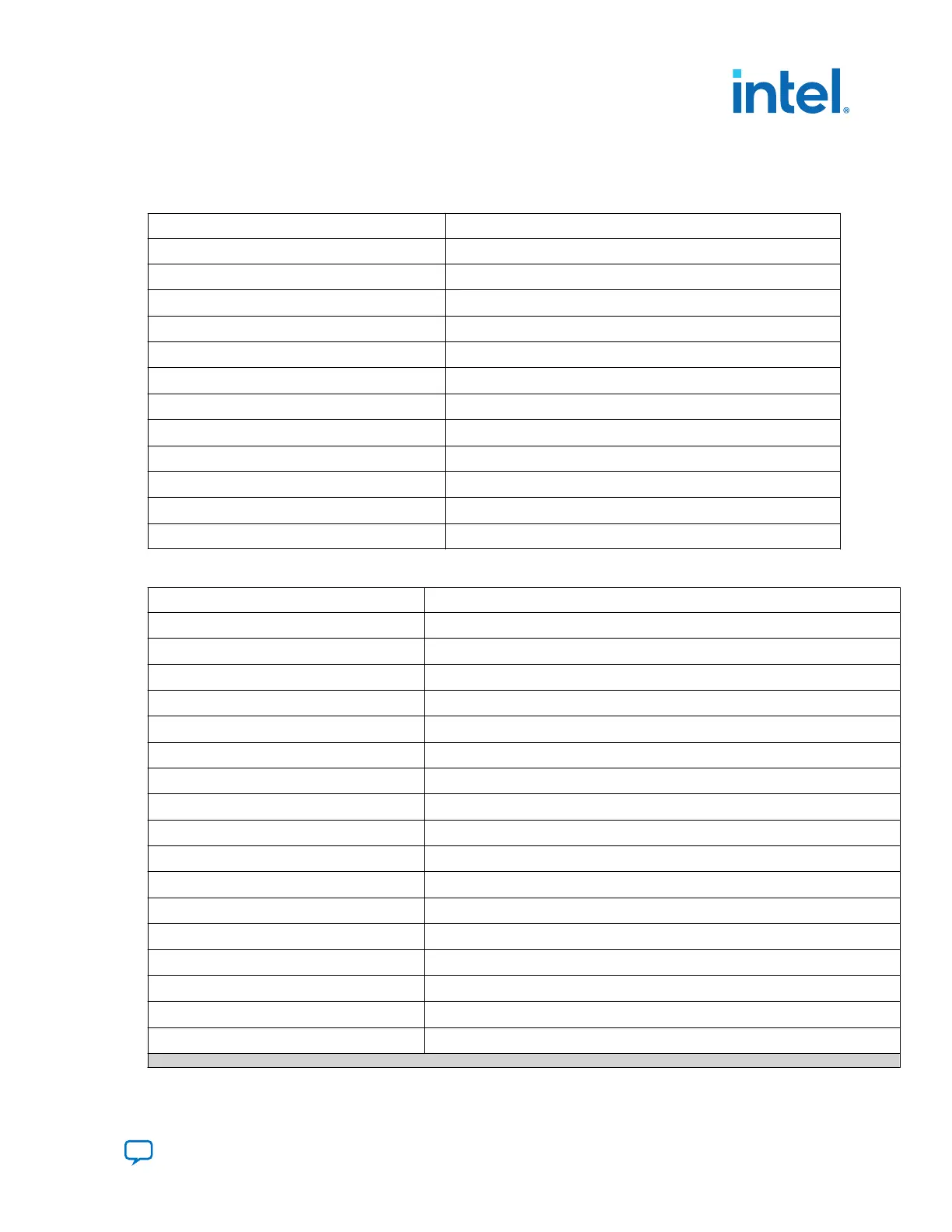
Table 9. Intel MAX 10 and FPGA
Schematic Signal Name Description
F_GPIO0 The value of filtered user_pb[0]
F_GPIO1 The value of filtered user_pb[1]
F_GPIO2
Reserved
F_GPIO3
Reserved
F_GPIO4
Reserved
F_GPIO5
Reserved
F_GPIO6
Reserved
F_GPIO7
Reserved
F_GPIO8
Reserved
F_GPIO9
Reserved
F_GPIO10
Used for DIP Switch
F_GPIO11
Used for Switch Data Transfer
Table 10. System Intel MAX 10
Schematic Signal Name Description
USER_PB0
User Push Button
USER_PB1
User Push Button
USER_SW0
User Switch
USER_SW1
User Switch
USER_SW2
User Switch
USER_SW3
User Switch
USER_SW4
User Switch
USER_SW5
User Switch
USER_SW6
User Switch
USER_SW7
User Switch
SYS_PWR_RSV3
Reserved GPIO between System Intel MAX 10 and Power Intel MAX 10
SYS_PWR_RSV2
Reserved GPIO between System Intel MAX 10 and Power Intel MAX 10
SYS_PWR_RSV1
Reserved GPIO between System Intel MAX 10 and Power Intel MAX 10
SYS_PWR_RSV0
Reserved GPIO between System Intel MAX 10 and Power Intel MAX 10
USER_LED0
User LED
USER_LED1
User LED
USER_LED2
User LED
continued...
A. Development Kit Components
776646 | 2023.05.31
Send Feedback
Intel Agilex
®
7 FPGA I-Series Transceiver (6 × F-Tile) Development Kit User
Guide
41

 Loading...


