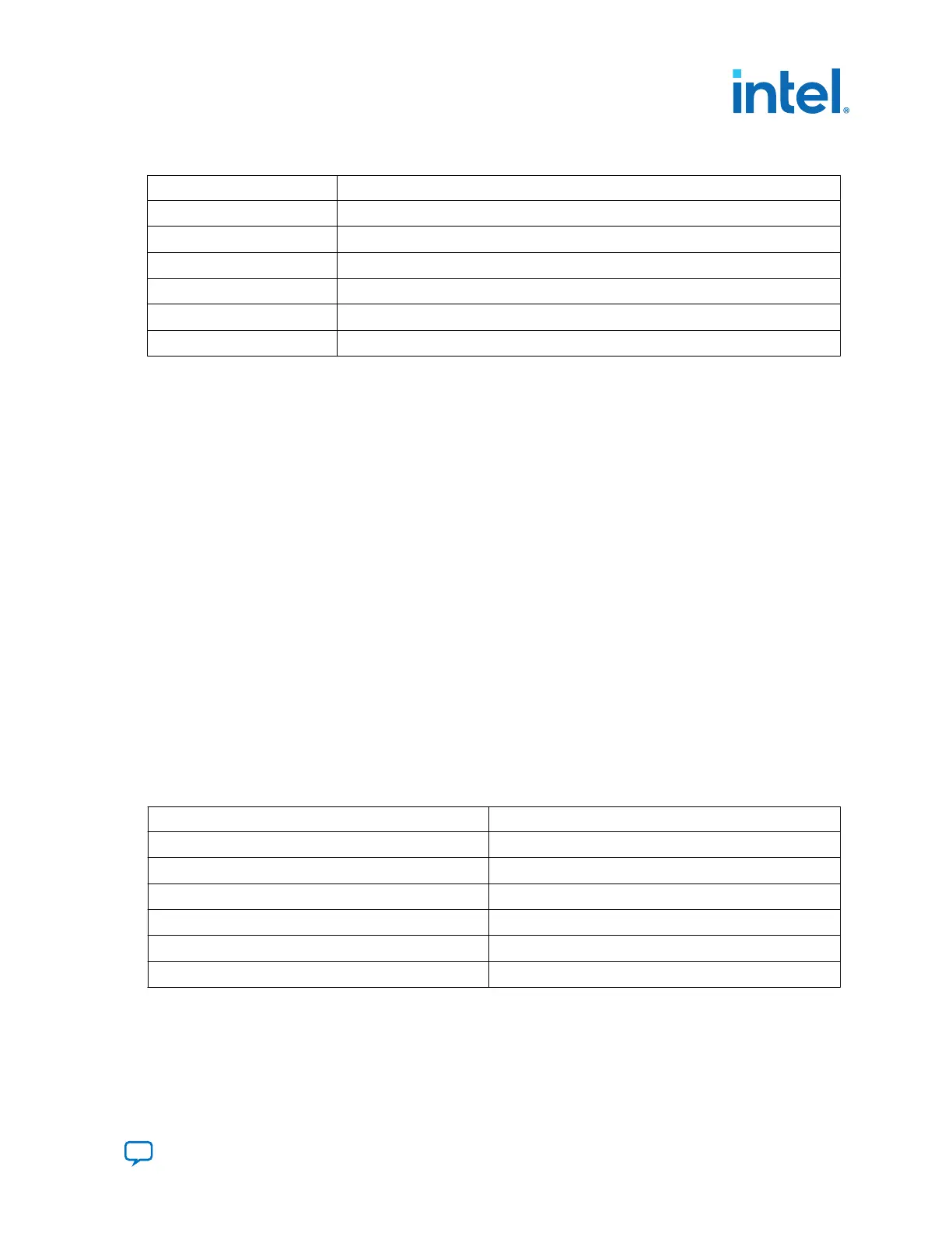
Table 11. UB2/PWR Intel MAX 10
Schematic Signal Name Description
FPGA_POK_LED
FPGA Power Good
SYS_PWR_RSV0
Reserved GPIO between System Intel MAX 10 and Power Intel MAX 10
SYS_PWR_RSV1
Reserved GPIO between System Intel MAX 10 and Power Intel MAX 10
SYS_PWR_RSV2
Reserved GPIO between System Intel MAX 10 and Power Intel MAX 10
SYS_PWR_RSV3
Reserved GPIO between System Intel MAX 10 and Power Intel MAX 10
PWR_PB0
POWER MAX PB0—FU
A.6. Memory Interfaces
FPGA dedicated external memory interface (1DPC DDR4)
Intel Agilex 7 FPGA I-Series Transceiver Development Kit supports 16GB 1DPC DDR4
with ECC support (x72). Mechanically, the development kit provides 1 Dual In Memory
Module slots for the same.
FPGA external memory interface (DDR4)
DDR4 component interface is a 72 bit, single rank configuration based on x16
component. It runs at 2666 MT/s. MT40A2G16SKL-062E:B or MT40A2G16TBB-062E:F
from Micron is soldered down on the development kit.
A.7. Communication Interfaces
MCIO Port (J37)
The MCIO slot is a PCIe Gen4 x4 port which fans out from Intel Agilex 7 I-Series FPGA
F-tile. This port is designed to meet the standard MCIO pinout.
System Intel MAX 10 acts as the board management controller (BMC) of the
development kit. It manages power up reset for both PCIe* root port and PCIe end
point. PCIE_1_PERSTn_A signal acts as output and input respectively.
Table 12. MCIO Port
Schematic Signal Name Description
PCIE_1_PERSTn_A
PCIe endpoint/rootport reset
PCIE_1_ALERTn_A
PCIe Alert
PCIE_100M_REF_AP/AN
PCIe reference clock
PCIE_1_SCL_A/SDA_A
PCIe I2C bus
PCIE_1_TX_[0:3]_DP/DN
Transceiver TX
PCIE_1_RX_[0:3]_DP/DN
Transceiver RX
QSFPDD
Intel Agilex 7 I-Series development kit supports 4x QSFPDD ports. QSFPDD port fans
out from the Intel Agilex 7 I-Series FPGA F-tile (FGT). All 8 channels per QSFPDD can
run up to 25 Gbps NRZ and 50 Gbps PAM4.
A. Development Kit Components
776646 | 2023.05.31
Send Feedback
Intel Agilex
®
7 FPGA I-Series Transceiver (6 × F-Tile) Development Kit User
Guide
45

 Loading...


