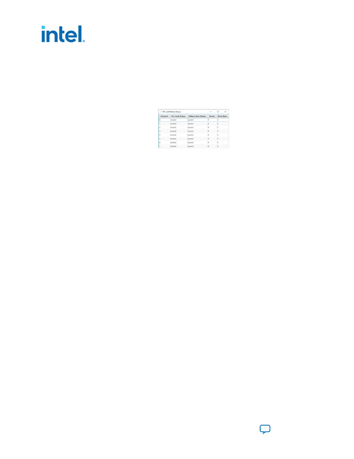
• PLL lock: Shows the PLL locked or unlocked state.
• Pattern Sync: Shows the pattern synced or not state. The pattern is considered
synced when the start of the data sequence is detected.
• Detail: Shows the PLL lock and pattern sync status of each channel. The number
of the error bits of each channel can be found here.
Figure 11. QSFPDD NRZ - PLL and Pattern Status
Control
Use the following controls to select an interface to apply PMA settings, data type and
error control:
• QSFPDD0 x8
• QSFPDD1 x8
• QSFPDD2 x8
• QSFPDD3 x8
PMA Setting
Allows you to make changes to the PMA parameters that affect the active transceiver
interface. The following settings are available for analysis:
• Serial Loopback: Displays the signal status between the transmitter and the
receiver.
• VOD: Specifies the voltage output differential of the transmitter buffer.
• Pre-emphasis tap:
— Pre-tap 1: Specifies the amount of pre-emphasis on the first pre-tap of the
transmitter buffer.
— Pre-tap 2: Specifies the amount of pre-emphasis on the second pre-tap of the
transmitter buffer.
— Post-tap 1: Specifies the amount of pre-emphasis on the post-tap of the
transmitter buffer.
4. Board Test System
776646 | 2023.05.31
Intel Agilex
®
7 FPGA I-Series Transceiver (6 × F-Tile) Development Kit User
Guide
Send Feedback
18

 Loading...


