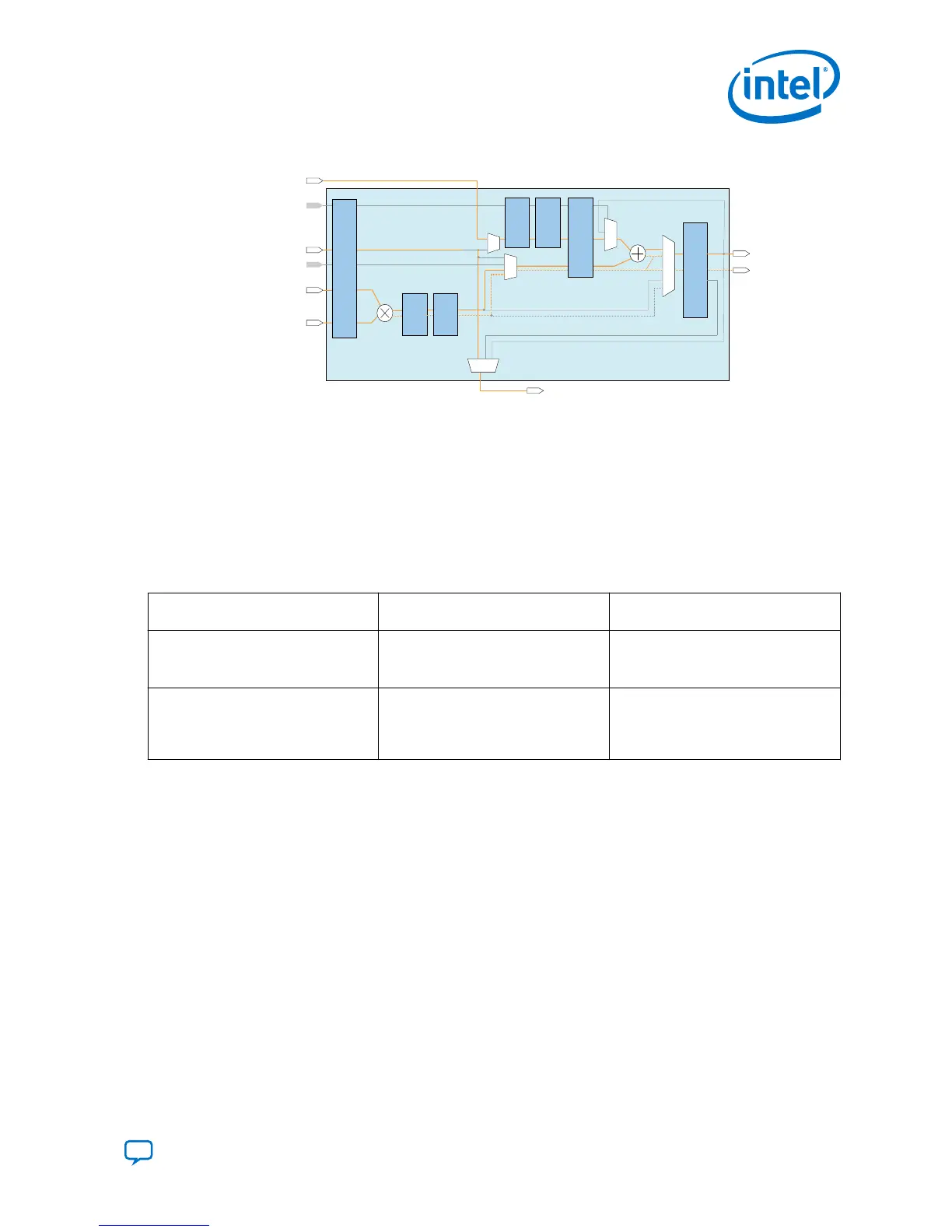
Figure 31. Vector One Mode
fp32_chainout[31:0]
fp32_chainin[31:0]
accumulate
fp32_adder_a[31:0]
fp32_mult_a[31:0]
fp32_mult_b[31:0]
Output
Register
Bank
Input
Register
Bank
fp32_result[31:0]
Multiplier
Adder
*Pipeline
Register
Bank
*Pipeline
Register
Bank
*Pipeline
Register
Bank
*Pipeline
Register
Bank
*Pipeline
Register
Bank
fp32_mult_invalid
fp32_mult_inexact
fp32_mult_overflow
fp32_mult_underflow
fp32_adder_invalid
fp32_adder_inexact
fp32_adder_overflow
fp32_adder_underflow
*This block diagram shows the functional representation of the DSP block.
The pipeline registers are embedded within the various circuits of the DSP block.
fp32_adder_b[31:0]
3.2.1.5. FP32 Vector Two Mode
This mode performs single-precision floating-point multiplication for input
fp32_mult_a and input fp32_mult_b, and direct the result to chainout. The chainin
input from the previous variable DSP Block is then added or subtracted from input
fp32_adder_a as the output result.
Table 17. Equations Applied to FP32 Vector Two Mode
Chainin Parameter Vector Two with Floating-Point
Addition
Vector Two with Floating-Point
Subtraction
Disable
result = fp32_adder_a
Chainout = fp32_mult_a *
fp32_mult_b
result = fp32_adder_a
Chainout = fp32_mult_a *
fp32_mult_b
Enable
result = fp32_adder_a +
fp32_chainin
Chainout = fp32_mult_a *
fp32_mult_b
result = fp32_adder_a -
fp32_chainin
Chainout = fp32_mult_a *
fp32_mult_b
The FP32 vector two mode supports the following exception flags:
•
fp32_mult_invalid
•
fp32_mult_inexact
•
fp32_mult_overflow
•
fp32_mult_underflow
•
fp32_adder_invalid
•
fp32_adder_inexact
•
fp32_adder_overflow
•
fp32_adder_underflow
3. Intel Agilex Variable Precision DSP Blocks Operational Modes
UG-20213 | 2019.04.02
Send Feedback
Intel
®
Agilex
™
Variable Precision DSP Blocks User Guide
43

 Loading...


