In the following table, up and down indicates the position of the switch with the
board orientation as shown in the Switch Locations and Default Settings for Power
Solution 1 figure.
Important: The default MSEL pin settings are set to all zeroes (ON) to select the
fast passive parallel x16 mode. For power-up configuration from MAX V
and CFI flash, ensure that the MAX V design uses this same mode as
does in the design in the cycloneVSX_5csxfc6df31_soc
\examples\max5 directory.
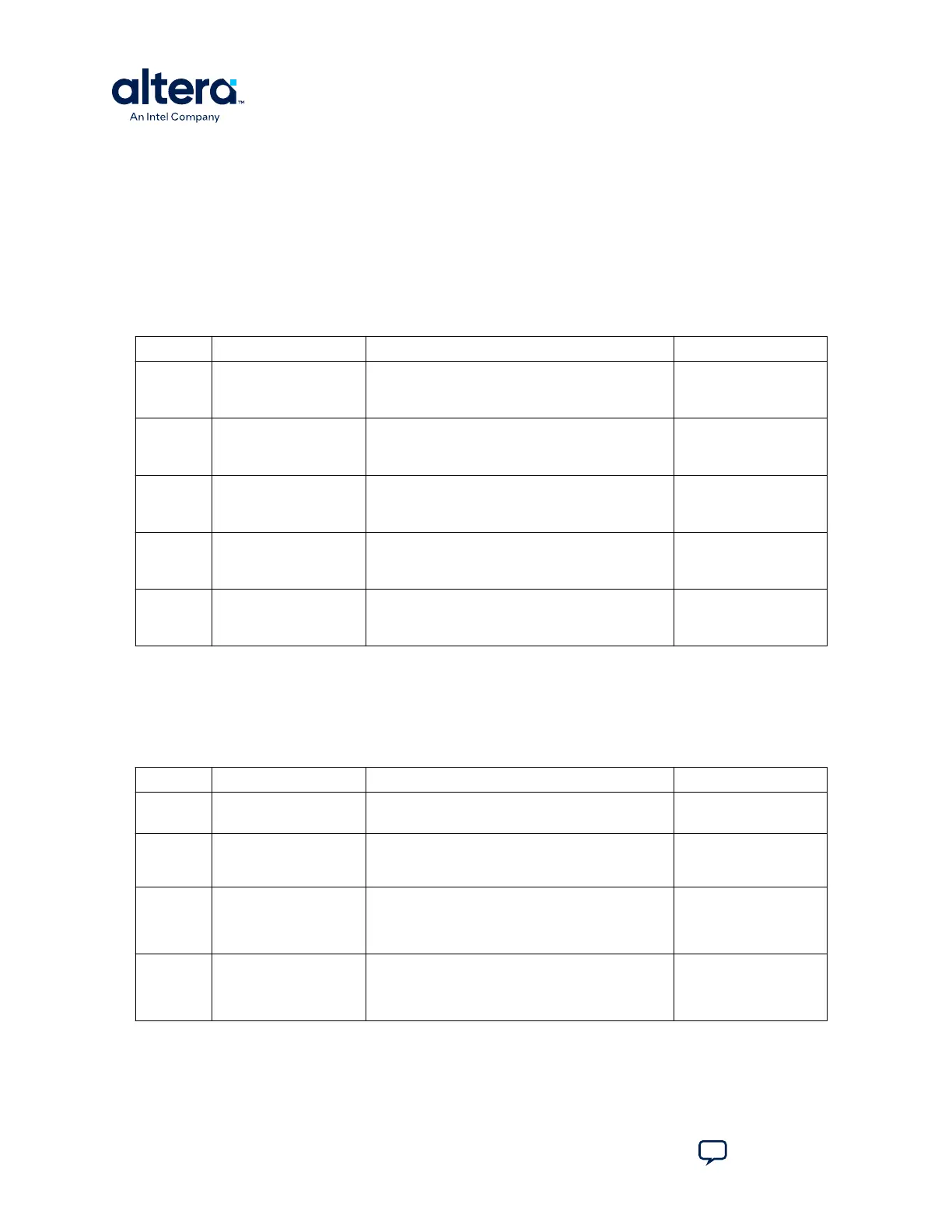
Table 9. SW3 DIP Switch Settings
Switch Board Label Function Default Position
1 MSEL0 Switch 1 has the following options:
• ON (up)—MSEL0 is 0.
• OFF (down)—MSEL0 is 1.
ON
2 MSEL1 Switch 2 has the following options:
• ON (up)—MSEL1 is 0.
• OFF (down)—MSEL1 is 1.
ON
3 MSEL2 Switch 3 has the following options:
• ON (up)—MSEL2 is 0.
• OFF (down)—MSEL2 is 1.
ON
4 MSEL3 Switch 4 has the following options:
• ON (up)—MSEL3 is 0.
• OFF (down)—MSEL3 is 1.
ON
5 MSEL4 Switch 5 has the following options:
• ON (up)—MSEL4 is 0.
• OFF (down)—MSEL4 is 1.
ON
3. Set the DIP switch bank (SW4) to match the SW4 JTAG DIP Switch Settings table.
In the following table, up and down indicates the position of the switch with the
board orientation as shown in the Switch Locations and Default Settings for Power
Solution 1 figure.
Table 10. SW4 JTAG DIP Switch Settings
Switch Board Label Function Default Position
1 HPS • ON (up)—Do not include HPS in the JTAG chain.
• OFF (down)—Include HPS in the JTAG chain.
OFF
2 FPGA • ON (up)—Do not include the FPGA in the JTAG
chain.
• OFF (down)—Include the FPGA in the JTAG chain.
OFF
3 HSMC • ON (up)—Do not include the HSMC connector in
the JTAG chain.
• OFF (down)—Include the HSMC connector in the
JTAG chain.
ON
4 MAX • ON (up)—Do not include the MAX V system
controller in the JTAG chain.
• OFF (down)—Include the MAX V system controller
in the JTAG chain.
OFF
4. Set the following jumper blocks to match the Default Jumper Settings for Power
Solution 1 Board table and the Switch Locations and Default Settings for Power
Solution 1 Board figure.
3. Development Kit Setup
830285 | 2024.10.07
Cyclone
®
V SoC Development Kit User Guide
Send Feedback
20