5.5. The Clock Control
The Clock Control application sets the Si570 or Si571 programmable oscillators to any
frequency between 10 MHz and 810 MHz and Si5338. The frequencies support eight
digits of precision to the right of the decimal point.
The Clock Control application runs as a stand-alone application. ClockControl.bat
resides in the cycloneVSX_5csxfc6df31_soc\examples\board_test_system
directory.
For more information about the Si570/Si571/Si5338 and the Cyclone V development
board's clocking circuitry and clock input pins, refer to the Cyclone V SoC
Development Board Reference Manual.
The Clock Control communicates with the MAX V device on the board through the
JTAG bus. The Si570, Si571, and Si5338 programmable oscillators are connected to
the MAX V device through a 2-wire serial bus.
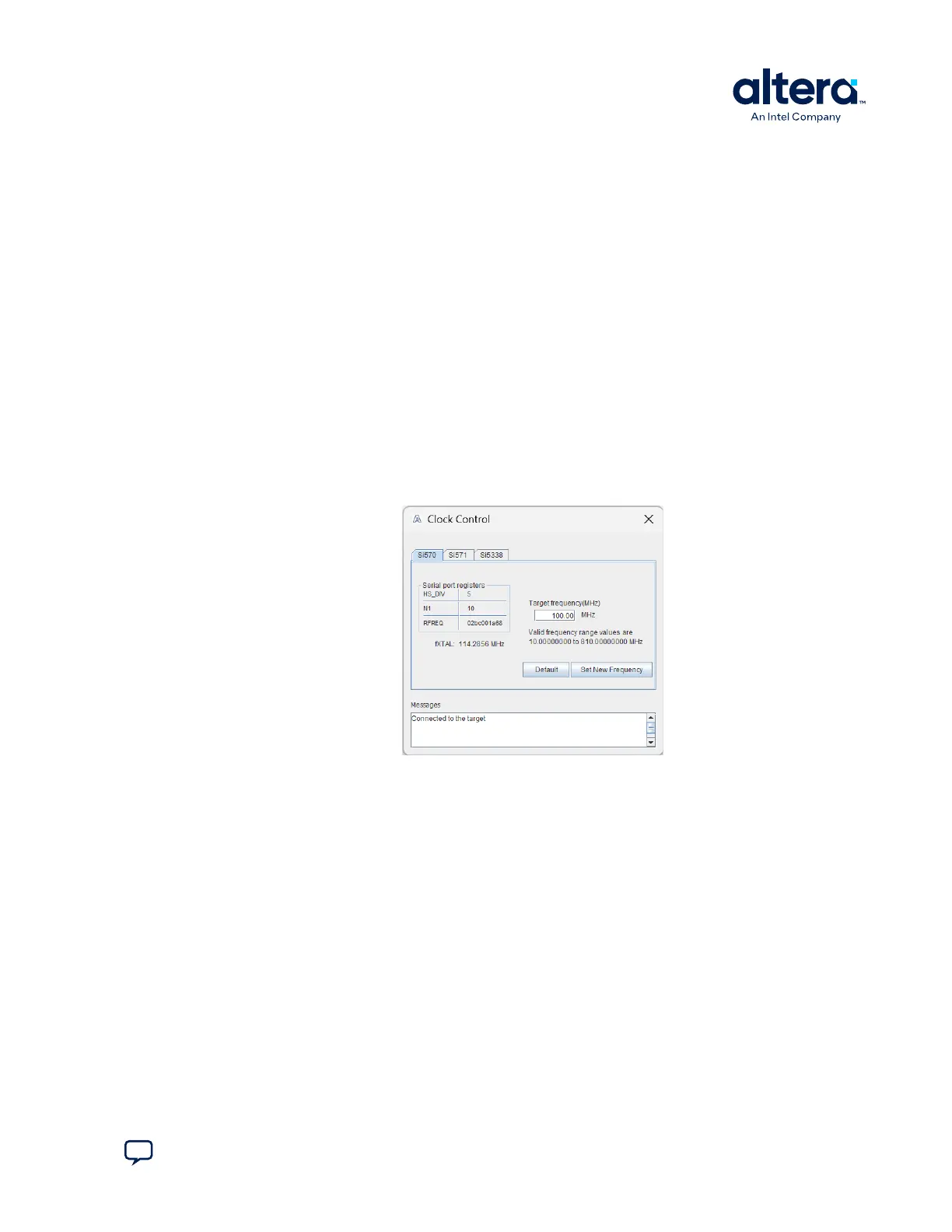
The following figure shows the Clock Control Si570 tab.
Figure 16. The Clock Control—Si570
The following sections describe the Clock Control controls.
Serial Port Registers
The Serial port registers control shows the current values from the Si570 registers.
For more information about the Si570 registers, refer to the Si570/Si571 data sheet
available on the Skyworks website.
fXTAL
The fXTAL control shows the calculated internal fixed-frequency crystal, based on the
serial port register values. For more information about the f
XTAL
value and how it is
calculated, refer to the Si570/Si571 data sheet available on the Skyworks website.
5. Board Test System
830285 | 2024.10.07
Send Feedback
Cyclone
®
V SoC Development Kit User Guide
41