5.4. The Power Monitor
The Power Monitor measures and reports current power information. To start the
application, click Power Monitor in the Board Test System application.
Attention:
You can also run the Power Monitor as a stand-alone application. PowerMonitor.bat
resides in the cycloneVSX_5csxfc6df31_soc\examples\board_test_system
directory.
The Power Monitor communicates with the MAX V device on the board through the
JTAG bus. A power monitor circuit attached to the MAX V device allows you to
measure the power that the Cyclone V FPGA is consuming.
Attention: The Power Monitor measures power over an I
2
C bus with multiple masters. You might
see some glitches in the measurements if the HPS is booted. The GSRD and other
Linux images access the I
2
C bus periodically and cause inaccurate measurements for a
cycle or two. These should go away and likely return to an accurate, steady state
measurement for most designs.
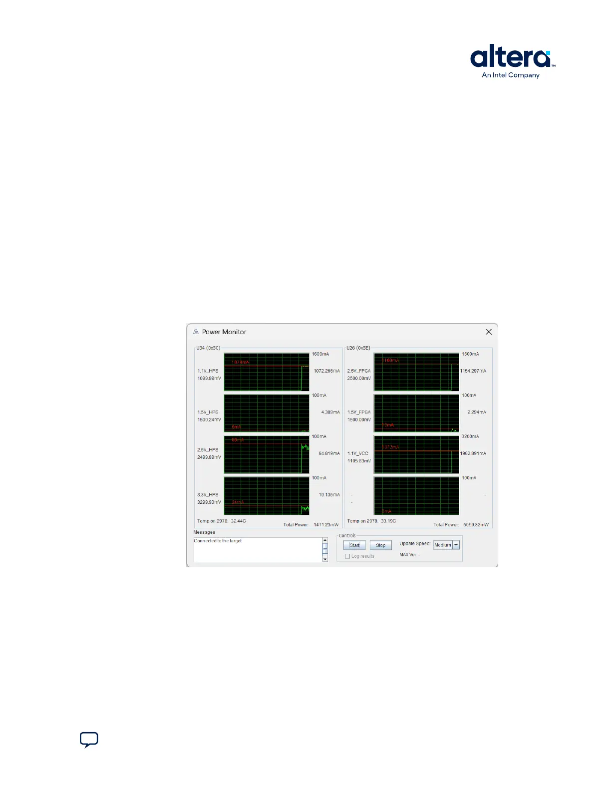
Figure 15. The Power Monitor
The following sections describe the Power Monitor controls.
U34 and U26
The U34 and U26 groups show the power rail graphs. They display the mA power
consumption of your board over time. The green line indicates the current value. The
red line indicates the maximum value read since the last reset.
Attention:
You can enlarge a graph by clicking on it. Click it again to restore the original size.
5. Board Test System
830285 | 2024.10.07
Send Feedback
Cyclone
®
V SoC Development Kit User Guide
39