Quad-Core Intel® Xeon® Processor 5300 Series Datasheet 25
Electrical Specifications
Notes:
1. Refer to Section 5 for signal descriptions.
2. These signals may be driven simultaneously by multiple agents (Wired-OR).
3. Not all Quad-Core Intel® Xeon® Processor 5300 Series support the additional signals A[37:36]#.
Processors that support these signals will be outlined in the Quad-Core Intel® Xeon® Processor 5300
Series NDA Specification Update.
Table 2-7 and Table 2-8 outline the signals which include on-die termination (R
TT
).
Table 2-7 denotes AGTL+ signals, while Table 2-8 outlines non AGTL+ signals including
open drain signals. Table 2-9 provides signal reference voltages.
Note:
1. Not all Quad-Core Intel® Xeon® Processor 5300 Series support the additional signals A[37:36]#.
Processors that support these signals will be outlined in the Quad-Core Intel® Xeon® Processor 5300
Series NDA Specification Update.
Note:
1. Signals that have a 50 Ω pullup to V
TT
on package.
TAP Input Synchronous to TCK TCK, TDI, TMS, TRST#
TAP Output Synchronous to TCK TDO
Power/Other Power/Other COMP[3:0], GTLREF_ADD_MID,
GTLREF_ADD_END, GTLREF_DATA_MID,
GTLREF_DATA_END, LL_ID[1:0], MS_ID[1:0],
PECI, RESERVED, SKTOCC#, TESTHI[11:10],
TESTHI[7:0], TESTIN1, TESTIN2, VCC,
VCC_DIE_SENSE, VCC_DIE_SENSE2, VCCPLL,
VID_SELECT, VSS_DIE_SENSE,
VSS_DIE_SENSE2, VSS, VTT, VTT_OUT,
VTT_SEL
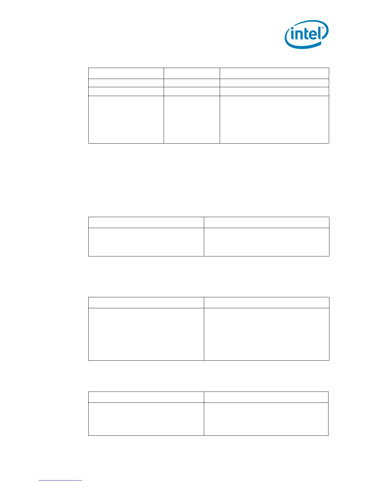
Table 2-6. FSB Signal Groups (Sheet 2 of 2)
Signal Group Type Signals
1
Table 2-7. AGTL+ Signal Description Table
AGTL+ signals with R
TT
AGTL+ signals with no R
TT
A[37:3]#
1
, ADS#, ADSTB[1:0]#, AP[1:0]#,
BINIT#, BNR#, BPRI#, D[63:0]#, DBI[3:0]#,
DBSY#, DEFER#, DP[3:0]#, DRDY#, DSTBN[3:0]#,
DSTBP[3:0]#, HIT#, HITM#, LOCK#, MCERR#,
REQ[4:0]#, RS[2:0]#, RSP#, TRDY#
BPM[5:0]#, BPMb[3:0]#, RESET#, BR[1:0]#
Table 2-8. Non AGTL+ Signal Description Table
Signals with R
TT
Signals with no R
TT
FORCEPR#
1
, PROCHOT#
1
A20M#, BCLK[1:0], BSEL[2:0], COMP[3:0], FERR#/
PBE#, GTLREF_ADD_MID, GTLREF_ADD_END,
GTLREF_DATA_MID, GTLREF_DATA_END, IERR#,
IGNNE#, INIT#, LINT0/INTR, LINT1/NMI, LL_ID[1:0],
MS_ID[1:0], PECI, PWRGOOD, SKTOCC#, SMI#,
STPCLK#, TCK, TDI, TDO, TESTHI[11:10], TESTHI[7:0],
TESTIN1, TESTIN2, THERMTRIP#, TMS, TRST#,
VCC_DIE_SENSE, VCC_DIE_SENSE2, VID[6:1],
VID_SELECT, VSS_DIE_SENSE, VSS_DIE_SENSE2,
VTT_SEL
Table 2-9. Signal Reference Voltages
GTLREF CMOS
A[37:3]#
1
, ADS#, ADSTB[1:0]#, AP[1:0]#,
BINIT#, BNR#, BPM[5:0]#, BPMb[3:0]#, BPRI#,
BR[1:0]#, D[63:0]#, DBI[3:0]#, DBSY#, DEFER#,
DP[3:0]#, DRDY#, DSTBN[3:0]#, DSTBP[3:0]#,
HIT#, HITM#, LOCK#, MCERR#, RESET#,
REQ[4:0]#, RS[2:0]#, RSP#, TRDY#
A20M#, FORCEPR#, IGNNE#, INIT#, LINT0/INTR,
LINT1/NMI, PWRGOOD, SMI#, STPCLK#, TCK, TDI,
TMS, TRST#