Quad-Core Intel® Xeon® Processor 5300 Series Datasheet 43
Electrical Specifications
Notes:
1. V
OS
is the measured overshoot voltage.
2. T
OS
is the measured time duration above VID.
2.13.3 Die Voltage Validation
Core voltage (VCC) overshoot events at the processor must meet the specifications in
Table 2-19 when measured across the VCC_DIE_SENSE and VSS_DIE_SENSE lands
and across the VCC_DIE_SENSE2 and VSS_DIE_SENSE2 lands. Overshoot events that
are < 10 ns in duration may be ignored. These measurements of processor die level
overshoot should be taken with a 100 MHz bandwidth limited oscilloscope.
2.14 AGTL+ FSB Specifications
Routing topologies are dependent on the processors supported and the chipset used in
the design. Please refer to the appropriate platform design guidelines for specific
implementation details. In most cases, termination resistors are not required as these
are integrated into the processor silicon. See Table 2-7 for details on which signals do
not include on-die termination. Please refer to Table 2-20 for R
TT
values.
Valid high and low levels are determined by the input buffers via comparing with a
reference voltage called GTLREF_DATA_MID, GTLREF_DATA_END, GTLREF_ADD_MID,
and GTLREF_ADD_END. GTLREF_DATA_MID and GTLREF_DATA_END are the reference
voltage for the FSB 4X data signals, GTLREF_ADD_MID and GTLREF_ADD_END are the
reference voltage for the FSB 2X address signals and common clock signals. Table 2-20
lists the GTLREF_DATA_MID, GTLREF_DATA_END, GTLREF_ADD_MID, and
GTLREF_ADD_END specifications.
The AGTL+ reference voltages (GTLREF_DATA_MID, GTLREF_DATA_END,
GTLREF_ADD_MID, and GTLREF_ADD_END) must be generated on the baseboard
using high precision voltage divider circuits. Refer to the appropriate platform design
guidelines for implementation details.
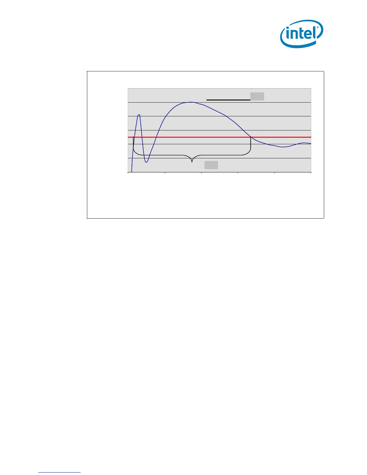
Figure 2-12. V
CC
Overshoot Example Waveform
Example Overshoot Waveform
0 5 10 15 20 25
Time [us]
Voltage [V]
VID - 0.000
VID + 0.050
V
OS
T
OS
T
OS
: Overshoot time above VID
V
OS
: Overshoot above VID