Signal Definitions
82 Quad-Core Intel® Xeon® Processor 5300 Series Datasheet
DSTBN[3:0]# I/O Data strobe used to latch in D[63:0]#. 3
DSTBP[3:0]# I/O Data strobe used to latch in D[63:0]#. 3
FERR#/PBE# O FERR#/PBE# (floating-point error/pending break event) is a multiplexed signal and
its meaning is qualified by STPCLK#. When STPCLK# is not asserted, FERR#/PBE#
indicates a floating-point error and will be asserted when the processor detects an
unmasked floating-point error. When STPCLK# is not asserted, FERR#/PBE# is similar
to the ERROR# signal on the Intel 387 coprocessor, and is included for compatibility
with systems using MS-DOS*-type floating-point error reporting. When STPCLK# is
asserted, an assertion of FERR#/PBE# indicates that the processor has a pending
break event waiting for service. The assertion of FERR#/PBE# indicates that the
processor should be returned to the Normal state. For additional information on the
pending break event functionality, including the identification of support of the feature
and enable/disable information, refer to Vol. 3 of the Intel® 64 and IA-32 Intel®
Architecture Software Developer’s Manual and the AP-485 Intel® Processor
Identification and the CPUID Instruction application note.
2
FORCEPR# I The FORCEPR# (force power reduction) input can be used by the platform to cause
the Quad-Core Intel® Xeon® Processor 5300 Series to activate the Thermal Control
Circuit (TCC).
GTLREF_ADD_MID
GTLREF_ADD_END
I GTLREF_ADD determines the signal reference level for AGTL+ address and common
clock input lands. GTLREF_ADD is used by the AGTL+ receivers to determine if a
signal is a logical 0 or a logical 1. Please refer to Table 2-20 and the appropriate
platform design guidelines for additional details.
GTLREF_DATA_MID
GTLREF_DATA_END
I GTLREF_DATA determines the signal reference level for AGTL+ data input lands.
GTLREF_DATA is used by the AGTL+ receivers to determine if a signal is a logical 0 or
a logical 1. Please refer to Table 2-20 and the appropriate platform design guidelines
for additional details.
HIT#
HITM#
I/O
I/O
HIT# (Snoop Hit) and HITM# (Hit Modified) convey transaction snoop operation
results. Any FSB agent may assert both HIT# and HITM# together to indicate that it
requires a snoop stall, which can be continued by reasserting HIT# and HITM#
together.
3
IERR# O IERR# (Internal Error) is asserted by a processor as the result of an internal error.
Assertion of IERR# is usually accompanied by a SHUTDOWN transaction on the
processor FSB. This transaction may optionally be converted to an external error
signal (e.g., NMI) by system core logic. The processor will keep IERR# asserted until
the assertion of RESET#.
This signal does not have on-die termination.
2
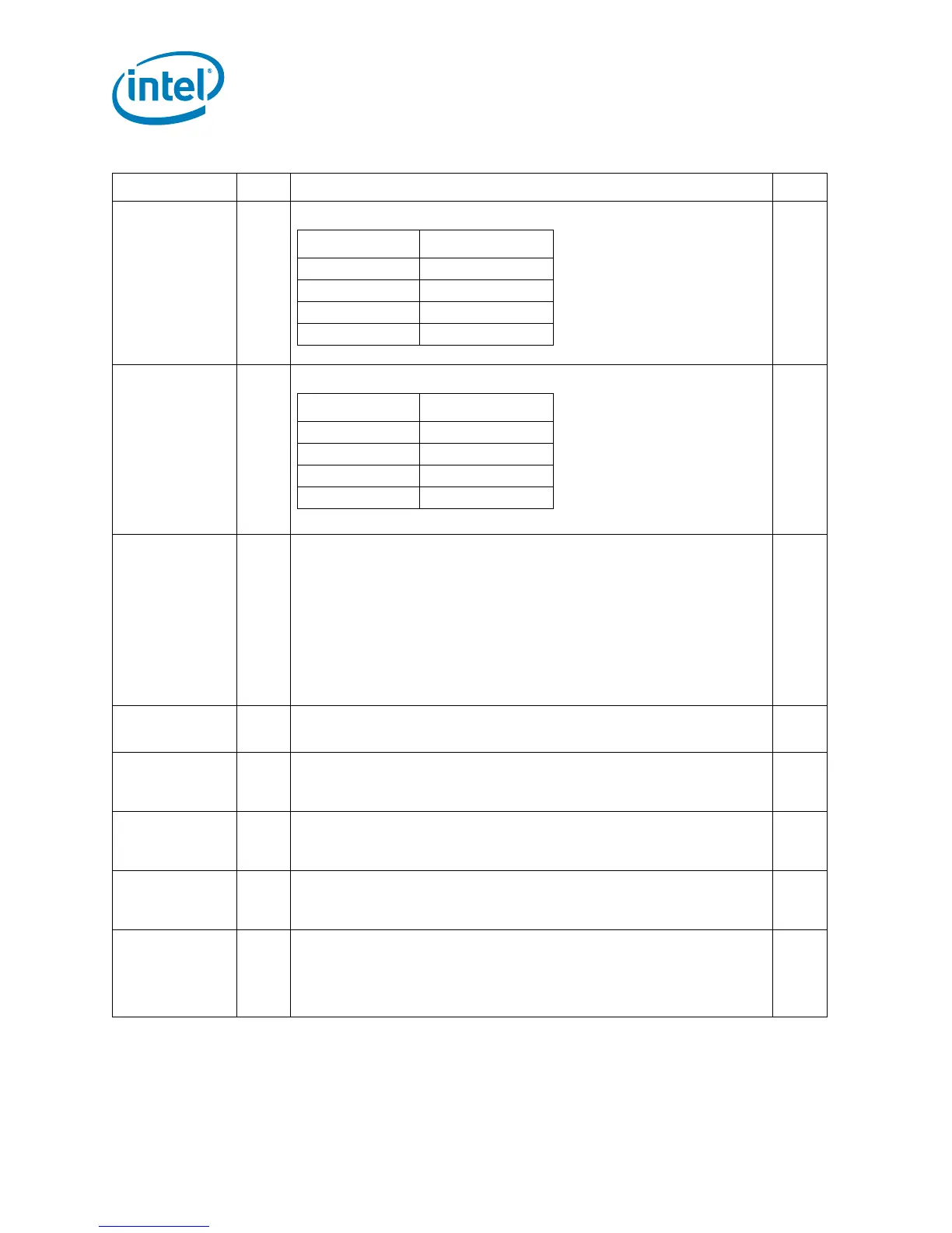
Table 5-1. Signal Definitions (Sheet 4 of 7)
Name Type Description Notes
Signals Associated Strobes
D[15:0]#, DBI0# DSTBN0#
D[31:16]#, DBI1# DSTBN1#
D[47:32]#, DBI2# DSTBN2#
D[63:48]#, DBI3# DSTBN3#
Signals Associated Strobes
D[15:0]#, DBI0# DSTBP0#
D[31:16]#, DBI1# DSTBP1#
D[47:32]#, DBI2# DSTBP2#
D[63:48]#, DBI3# DSTBP3#