Connector / Header Locations and Pin-outs Intel
®
Server Board S5500BC TPS
Intel order number: E42249-003 Revision 1.0
56
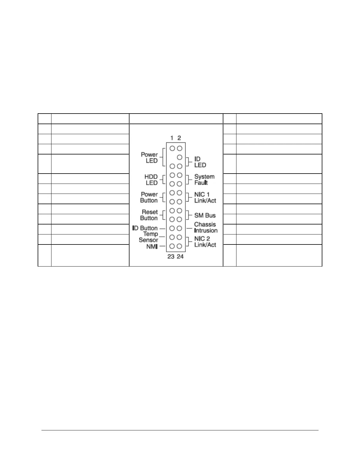
5.5 SSI Front Panel Connector
The Intel
®
Server Board S5500BC provides a 24-pin SSI control panel connector (J9E2) for use
with a non-Intel chassis. Several LEDs, such as the power status LED, HDD LED, and LAN
status LED, are provided on the front panel to provide a visual status. The following table
provides the pin-out information for this connector.
Table 16. Front Panel SSI Standard 24-pin Connector Pin-out (J9E2)
Pin Signal Name Control Panel Pin-out Pin Signal Name
1 P3V3_STBY 2 P3V3_STBY
3 Key 4 P5V_STBY
5 FP_PWR_LED_N_R 6 FP_ID_LED_R1_N
7
P3V3((HDD Activity LED
Anode)
8 LED_STATUS_GREEN_R_N
9 LED_HDD_ACTIVITY_R_N 10 LED_STATUS_AMBER_R_N
11 FP_PWR_BTN_R_N 12 P3V3_STBY
13 GND(Power Button GND) 14 LED_NIC1_LINK_ACT_BUF_R_N
15 RST_IBMC_RST_BTN_N 16 SMB_SEN_3V3SB_DAT
17 GND (Reset GND) 18 SMB_SEN_3V3SB_DAT
19 FP_ID_BTN_R_N 20 FM_IBMC_INTRUDER_HDR
21 PU_FM_SIO_TEMP_SENSOR 22 P3V3_STBY
23 FP_NMI_BTN_R_N 24 LED_NIC0_LINK_ACT_BUF_R_N
5.6 I/O Connector Pin-out Definition
5.6.1 VGA Connector
The following table details the pin-out of the VGA connector (J7A1).