Intel
®
Server Board S5500BC TPS Connector / Header Locations and Pin-outs
Revision 1.0 Intel order number: E42249-003 59
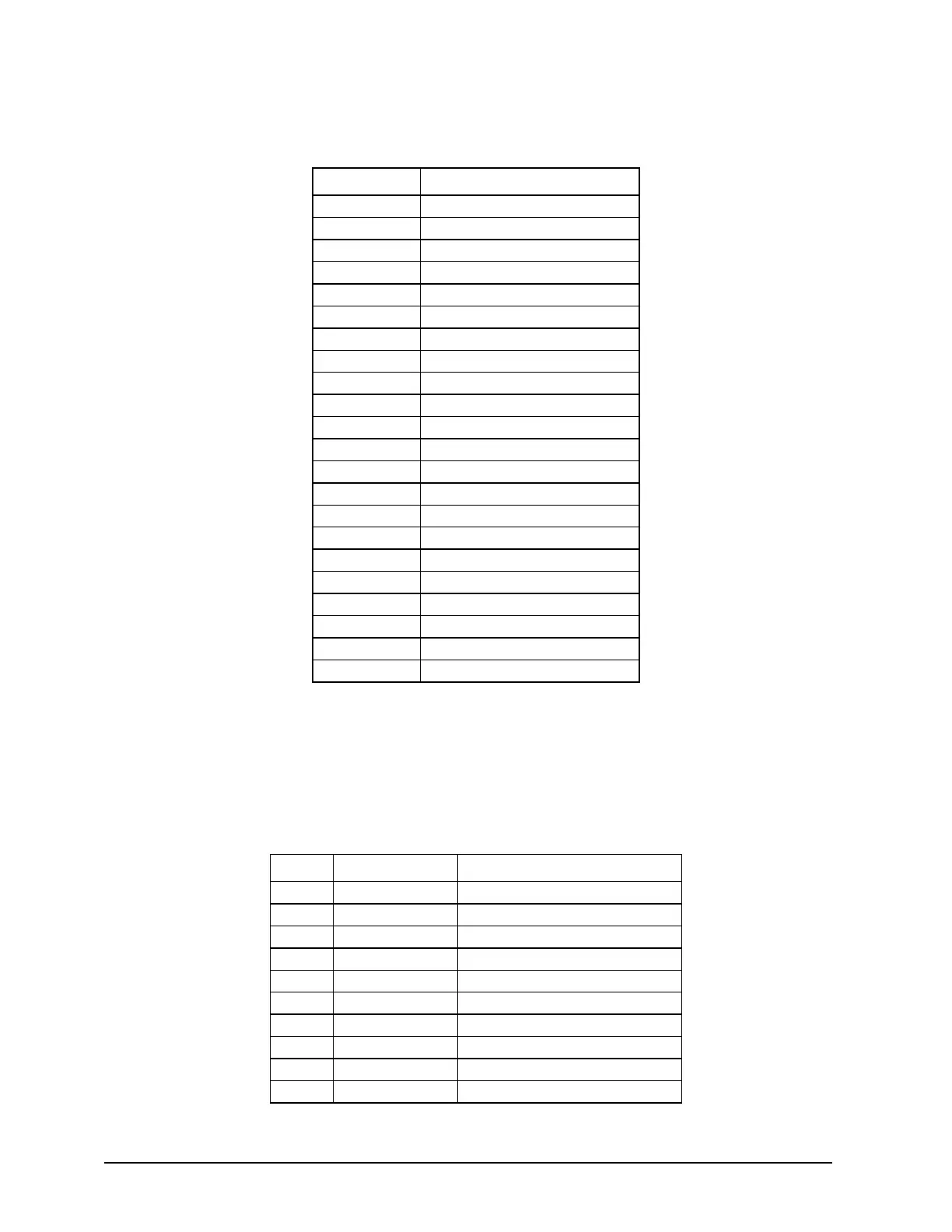
Table 21. External USB and GbE connector Pin-out (J5A1, J6A1)
Pin Signal Name
1 USB PWR
2 USBP_1N
3 USBP_1P
4 GND
5 USB PWR
6 USB_0N
7 USB_0P
8 GND
9 TERM
10 MDI0P
11 MDI0N
12 MDI1P
13 MDI1N
14 MDI2P
15 MDI2N
16 MDI3P
17 MDI3N
18 GND
19 GRN_C
20 GRN_A
21 GRN_C/YEL_A
22 GRN_A/YEL_C
Four ports are connected to the two 2x5 headers (J1A3, J2A2) on the Intel
®
Server Board
S5500BC. The following table provides the pin-out information for the header. The two headers
are identical.
Table 22. Internal USB Header Pin-out (J1A3, J2A2)
Pin Signal Name Description
1 USB PWR USB Power
2 USB PWR USB Power
3 USB_5N USB Port 5 Negative Signal
4 USB_6N USB Port 6 Negative Signal
5 USB_5P USB Port 5 Positive Signal
6 USB_6P USB Port 6 Positive Signal
7 Ground Ground
8 Ground Ground
9 Key N/A
10 NC No Connection