Intel
®
Server Board S5500BC TPS Connector / Header Locations and Pin-outs
Revision 1.0 Intel order number: E42249-003 61
5.8 SGPIO Header
One 4-Pin SGPIO Connector (J1C1).
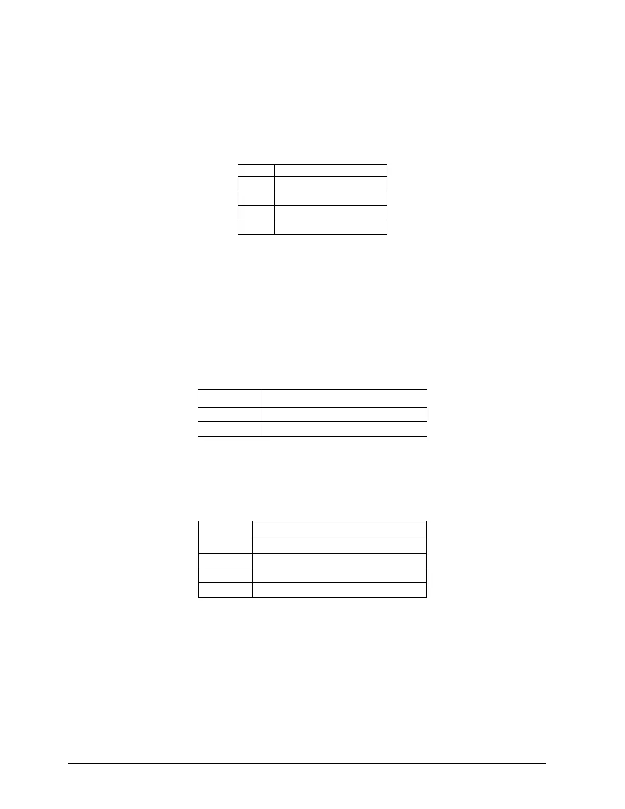
Table 24. SGPIO connector Pin-out (J1C1)
Pin Signal Name
1 SCLK
2 SLOAD
3 SDATAOUT0
4 SDATEOUT1
5.9 Chassis Intrusion Header
A 2-pin Chassis intrusion header (J8B3) is provided. This is intended to support micro switches
that close, making a connection to ground when the chassis is opened or removed. The
intrusion signal is routed to the Integrated BMC internal intrusion circuit, which resides in the
RTC well.
Table 25. Chassis Intrusion connector Pin-out (J8B3)
Output Signal Name
To BMC FM_IBMC_INTRUDER_HDR_N
To FP FM_IBMC_INTRUDER_HDR
5.10 SMB Hot-Swap Backplane (HSBP) Header
Table 26. SMB HSBP connector Pin-out (J9B1)
Pin Signal Name
1 SMB_HSBP_5V_DAT
2 GND
3 SMB_HS BP_5V_CLK
4 P5V Pull-up