Rotary Chair Instruction for Use - English
Date: 2011-09-27 Page 14
Hardware installation
The rotary chair must be secured to the floor with 4 screws
through the bottom rim of the base. Please use 12 mm dowels
and 8 x 120 mm screws.
The Patient is not allowed to sit on the calves-area of the chair when
this has been reclined into its horisontal position
Never connect the instrument to the power outlet before the side panels
and the top cover have been correctly refitted and secured.
Consult with the product specification plate on the unit for compliance between the unit’s own data and
those of the local power supply system (mains voltage and mains frequency) before connecting the
unit.
Connect only if all data agrees!
Inspect the mains connection cables for visible damage prior to establishing the connection. Damaged
cables or plugs must immediately be replaced by Interacoustics service technicians, an authorized
person or specialist.
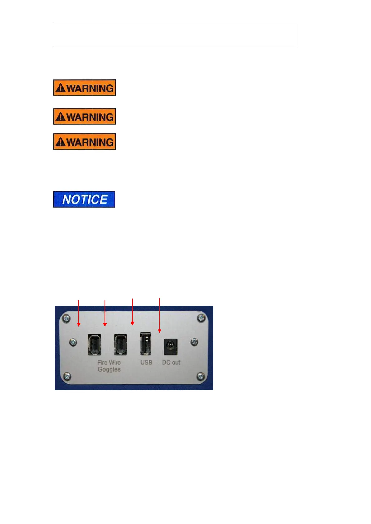
Connection Panel
The backrest features a connection panel with purpose specific connections:
Input/output connection panel , back rest
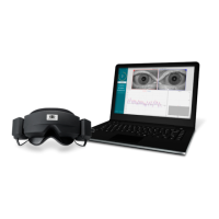
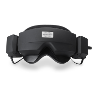
FireWire® interface for
the camera(s) mounted in
the goggles