52 | Optidrive P2 User Guide | Version 3.00 www.invertekdrives.com
8.2.6. Syn RM Synchronous Reluctance Motors
When operating with Synchronous Reluctance motors, carry out the following steps.
Ensure advanced parameter access is enabled by setting P1-14 = 101.
Enter the motor nameplate details into the relevant parameters as follows:
o P1-07 Motor Rated Voltage.
o P1-08 Motor Rated Current.
o P1-09 Motor Rated Frequency.
o (Optional) P1-10 Motor Rated Speed (Rpm).
o P4-05 Motor Power Factor.
Select Synchronous Reluctance Motor Control mode by setting P4-01 = 6.
Ensure that the motor is correctly connected to the drive.
Carry out a motor data Autotune by setting P4-02 = 1.
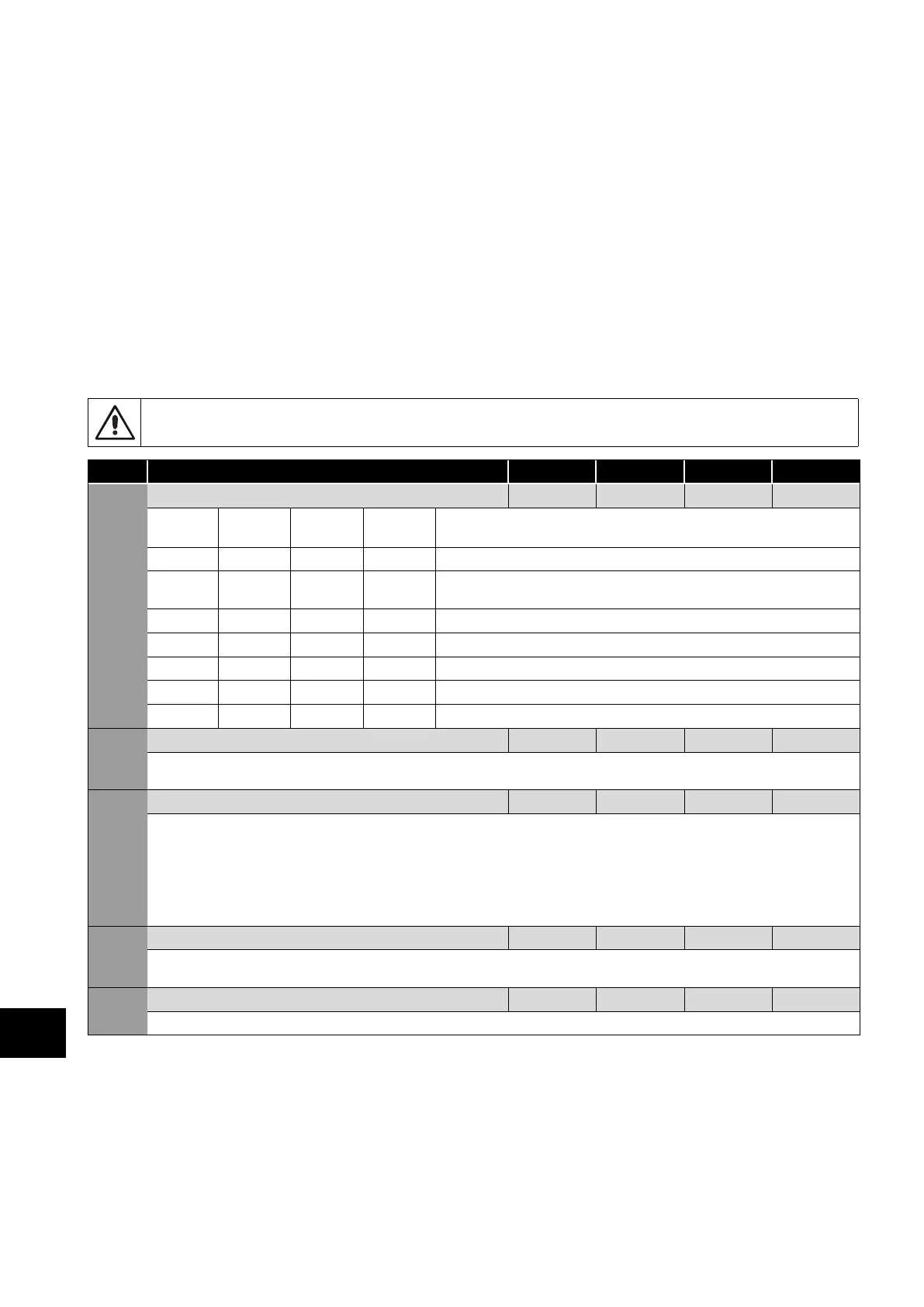
8.2.7. Group 4 Parameter Listing
Incorrect adjustment of parameters in menu group 4 can cause unexpected behaviour of the motor and any connected
machinery. It is recommended that these parameters are only adjusted by experienced users.
Par Parameter Name Minimum Maximum Default Units
P4-01 Motor Control Mode 0 6 2 -
Setting
Motor
Type
Primary
Control
Control
Method
Additional Information
0 IM Speed Vector Speed control with Torque Limit. Torque Limit Source selected by P4-06.
1 IM Torque Vector
Torque Control with Speed Limit. Torque reference selected by P4-06.
Speed Limit defined by the Speed Reference.
2 IM Speed V/F V/F control for simple applications with standard IM Motors.
3 AC PM Speed Vector For speed control of AC PM motors with Sinusoidal back EMF.
4 AC PM Torque Vector For torque control of AC PM motors with Sinusoidal back EMF.
5 BLDC Speed Vector For speed control of BLDC motors with Trapezoidal back EMF.
6 Syn RM Speed Vector For speed control of Synchronous Reluctance motors.
P4-02 Motor Parameter Auto-tune Enable 0 1 0 -
When set to 1, the drive immediately carries out a non-rotating autotune to measure the motor parameters for optimum control and
efficiency. Following completion of the autotune, the parameter automatically returns to 0.
P4-03 Vector Speed Controller Proportional Gain 0.1 400.0 25.0 %
Sets the proportional gain value for the speed controller when operating in Vector Speed or Vector Torque motor control modes (P4-01
= 0 or 1). Higher values provide better output frequency regulation and response. Too high a value can cause instability or even over
current trips. For applications requiring best possible performance, the value should be adjusted to suit the connected load by gradually
increasing the value and monitoring the actual output speed of the load until the required dynamic behaviour is achieved with little or
no overshoot where the output speed exceeds the setpoint.
In general, higher friction loads can tolerate higher values of proportional gain, and high inertia, low friction loads may require the gain
to be reduced.
P4-04 Vector Speed Controller Integral Time Constant 0.000 2.000 0.050 s
Sets the integral time for the speed controller. Smaller values provide a faster response in reaction to motor load changes, at the risk of
introducing instability. For best dynamic performance, the value should be adjusted to suit the connected load.
P4-05 Motor Power Factor Cos Ø 0.50 0.99 - -
When operating in Vector Speed motor control modes, this parameter must be set to the motor nameplate power factor.
8
Extended Parameters
 Loading...

